Holding means for holding two parts on each other

a technology for holding two parts and parts, applied in the direction of chucks, manufacturing tools, metal-working machine components, etc., can solve the problems of inability to seal off, inability to fully control the raising and lowering, and substantial danger of foreign matter deposits

Inactive Publication Date: 2004-03-11
MASCHFAB BERTHOLD HERMLE
View PDF5 Cites 22 Cited by
  • Summary
  • Abstract
  • Description
  • Claims
  • Application Information

AI Technical Summary

Benefits of technology

[0004] One object of the invention is to create a holding means of the type initially mentioned in the case of which the ingress of lubricants and dirt as well the collection thereof may be prevented.
[0006] Owing to the configuration provided by the invention of the clamping element same may be provided with a sealing ring so that the ingress of lubricants and other foreign matter may be effectively prevented. Simultaneously the sealing ring prevents the clamping element dropping out of its guide hole so that there is an additional means for preventing falling out, as for example swaging, is unnecessary. The geometry of the clamping element ensures a linear guide action so that the axial clamping force of the sliding element may be split up into an axial and a radial force component. The radial force component then assumes the function of positioning (centering and clamping) in the horizontal plane. On the other hand the balls, as in past designs, may only clamp or hold tight and do not position or center the work. Owing to the two hemispherical terminal regions the clamping elements are guided by means of two spaced apart ring edges in the through hole so that skew running is prevented.
[0008] One of the two terminal regions of the clamping element, and more especially the outwardly facing terminal region, may have a flat which preferably in the non-clamped setting is substantially aligned with the outer face of the shape element. Accordingly the overall length can be reduced and a satisfactory linear guiding action may be ensured.
[0014] A further effective measure for the prevention of soiling and the building up of deposits of dirt is such that the shape element and / or the sliding element contain at least one fluid pressure duct whose at least one blow-off opening is directed toward the recess in the cooperating part. By deflection of the pressure jet into the recess dirt, shavings and lubricants will be removed from the recess, from the shape element and from the centering bolster faces or, respectively, reference faces so that an accurate lowering into place is ensured. By regular operation of this pressure jet on lowering into position deposits are furthermore effectively prevented. Preferably in the case of a bell-like design of the recess in the cooperating part it is possible for such jet and its deflection to be so optimized that optimum cleaning is ensured. This measure as well is claimed as a subcombination independently of the features of claims 1 and 4.
[0015] Furthermore it has been found to be an advantage to associate with the pressure duct a volumetric flow measuring means for checking the position, such volumetric flow measuring means being more particularly activated prior to reaching the clamping position and / or in the clamping position. The volumetric flow constitutes a measure for the movement together of the two parts so that the correct seat in the clamping position can be checked in a simple manner.

Problems solved by technology

On the other hand they are not able to be sealed off to prevent cooling lubricant and fragments produced by machining making their way into the clamping system.
Furthermore, the contact face between the bolster and the cooperating part is extremely large so that in this case as well the danger of deposits of foreign matter collecting is substantial.
Full control of raising and lowering is not possible so that on putting down the top part the contact face may be damaged.
Preliminary centering or positioning is limited in an unsatisfactory manner.
Owing to the sliding elements entering from above the building up of deposits of falling shavings and lubricating coolants can only be prevented with difficulty.
Owing to the necessary energy storing spring the entire arrangement becomes complex and expensive and furthermore liable to defects and rapid wear.
Since the balls may not be sealed off separately, all adjacent components must be sealed off in a complex fashion.
Moreover, preliminary centering and alignment is only possible to an extremely limited extent.
Sealing off of the clamping tongs against the ingress of dirt is extremely elaborate and accordingly unsatisfactory.

Method used


Image

  • Holding means for holding two parts on each other
  • Holding means for holding two parts on each other
  • Holding means for holding two parts on each other

Examples


Embodiment Construction

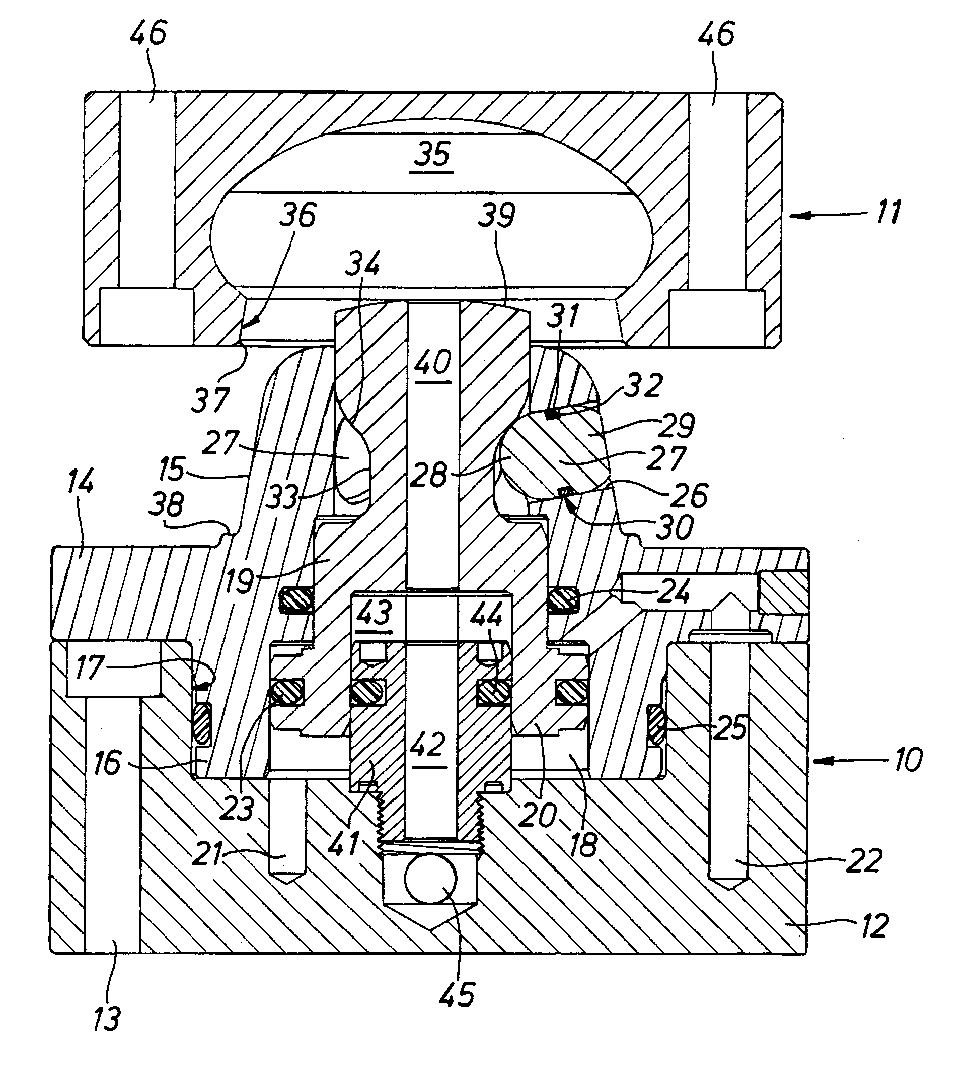
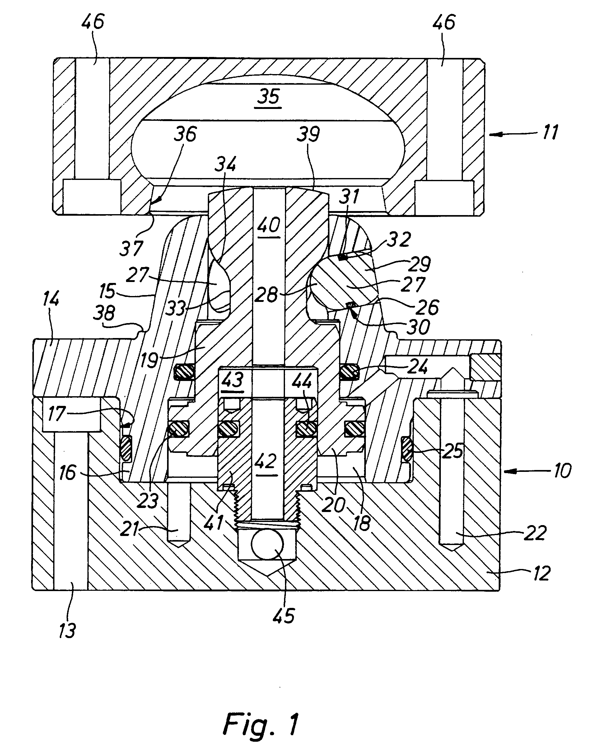
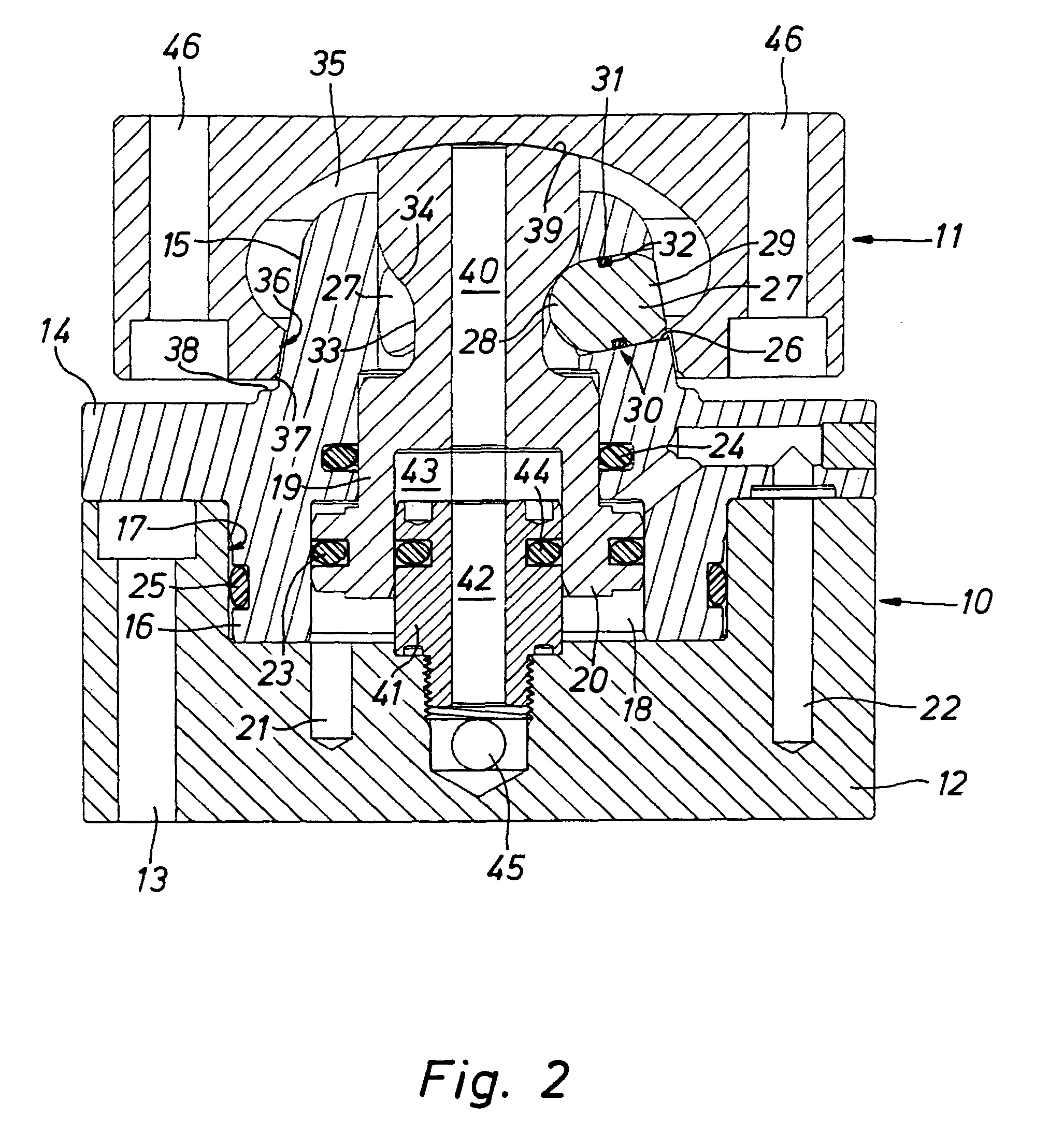
[0020] The holding means represented in various different working positions comprises essentially a bottom bolster 10 and a top cooperating part 11, which may be clamped together. The bottom bolster 10 may be screwed to a first part (not illustrated) and the cooperating part 11 may be screwed to a second part (not illustrated) so that such two parts may be clamped together with the aid of the holding means or, respectively, fixed together. For this purpose there is a plurality of such holding means, as for example three or four thereof. Accordingly for example workpieces may be fixed as a second part on a workpiece table as a second part in a predetermined position. The workpieces may also be secured to a workpiece palette in order to secure the cooperating part 11 to the workpiece table. A further alternative is such that on the workpiece table a clamping plate is fixed which is provided with bolsters 10 so that the workpiece palette or, respectively, the workpieces may be secured ...


PUM


Abstract

A clamping means for clamping two parts which more particularly serves for fixing a workpiece palette on a workpiece table. A bolster provided with a projecting shape element is secured to the first part and a cooperating part provided with a recess for receiving the shape element is secured to the second part. In the projecting shape element a sliding element runs which has at least one peripheral recess, into which at least one clamping element clamping means, which is able to be moved in a through hole in the shape element, fits in the non-clamping position, and on sliding the sliding element the clamping element is thrust outward into the clamping position, in which it interlocks in the recess in the cooperating part. The clamping element possesses a central guide for linearly guiding in the through hole, such guide region being provided with an annular groove to accommodate a sealing ring, hemispherical terminal regions being formed on either side of the guide region. The clamping element ensures on the one hand a reliable sealing action and on the other hand prevent the clamping element dripping out. Simultaneously a centering and clamping function is produced.

Description

[0001] The invention relates to a holding means for holding two parts together and more especially for fixing a workpiece palette on a workpiece table, comprising a bolster able to be secured to the first part, such bolster possessing a projecting shape element, a cooperating part adapted to be secured to the second part, such cooperating part possessing a recess to receive the shape element, and a sliding element running in the projecting shape element, such sliding element possessing at least one peripheral recess into which at least one clamping element, which is able to be moved in a through hole in the shape element, fits in the non-clamped state, sliding of the sliding element causing the clamping element to be thrust outward into a clamping position thereof, in which it interlocks with the cooperating part in the recess thereof.THE PRIOR ART[0002] In the case of a prior art holding means disclosed in the German patent publication 19,917,146 A1 of this type the clamping elemen...

Claims


Application Information

Patent Timeline
Patent Type & Authority Applications(United States)
IPC IPC(8): B23B31/107B23Q1/00B23Q3/18B23Q11/00
CPCB23B31/107B23Q11/005B23Q3/183B23Q1/0081B23B31/1078
Inventor BERNHARD, FRANZ-XAVERKOHLER, RAINER
Owner MASCHFAB BERTHOLD HERMLE
Why Eureka
Try Eureka