Instrumentation assembly for an offshore riser

a technology of instrumentation and riser, which is applied in the direction of instruments, survey, borehole/well accessories, etc., can solve the problem that the computer program is currently not completely validated for extreme conditions

Inactive Publication Date: 2006-07-25
INST FR DU PETROLE
View PDF14 Cites 49 Cited by
  • Summary
  • Abstract
  • Description
  • Claims
  • Application Information

AI Technical Summary

Problems solved by technology

However, at such depths, the problems are such that the computing programs are curr

Method used


Image

  • Instrumentation assembly for an offshore riser
  • Instrumentation assembly for an offshore riser
  • Instrumentation assembly for an offshore riser

Examples


Embodiment Construction

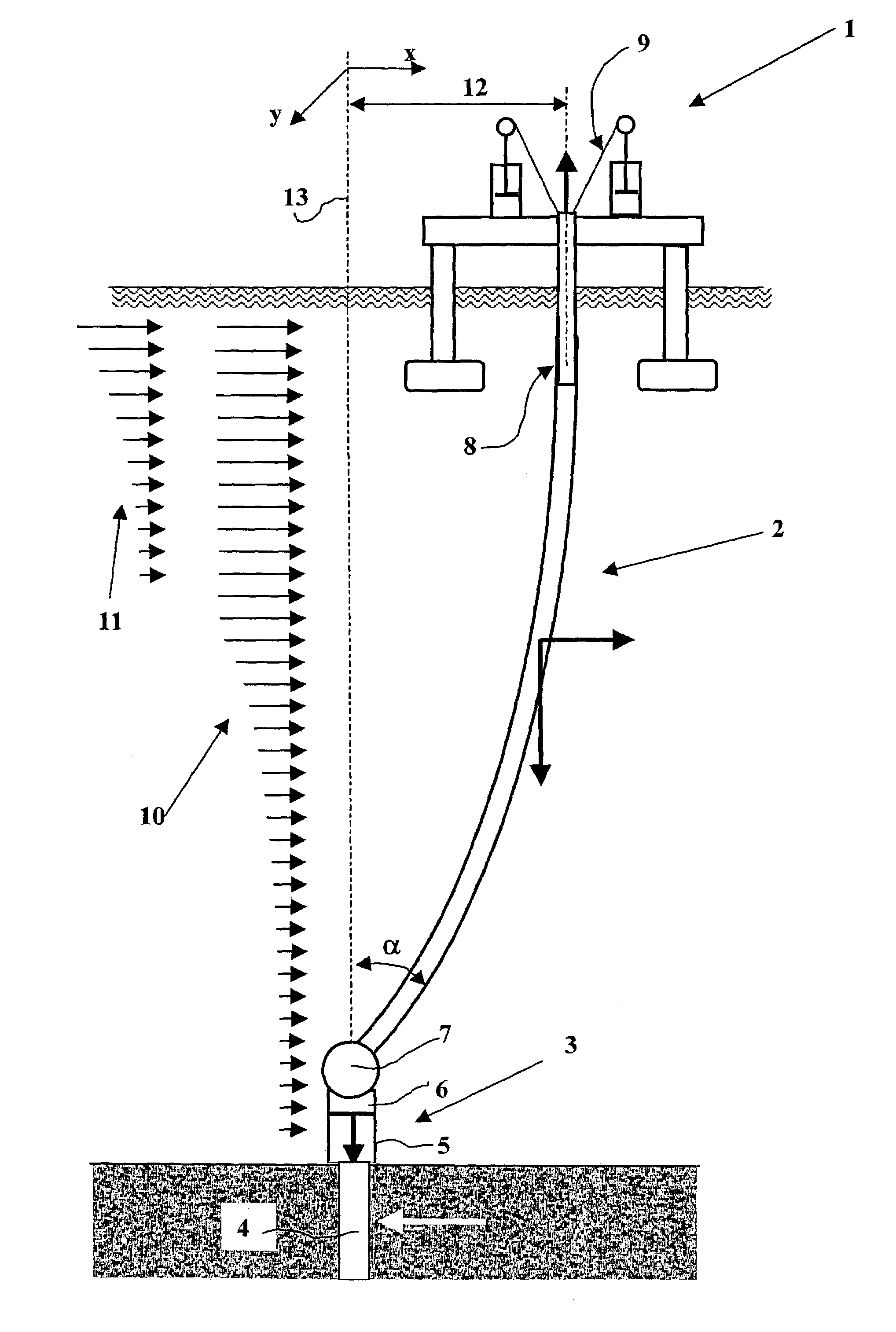
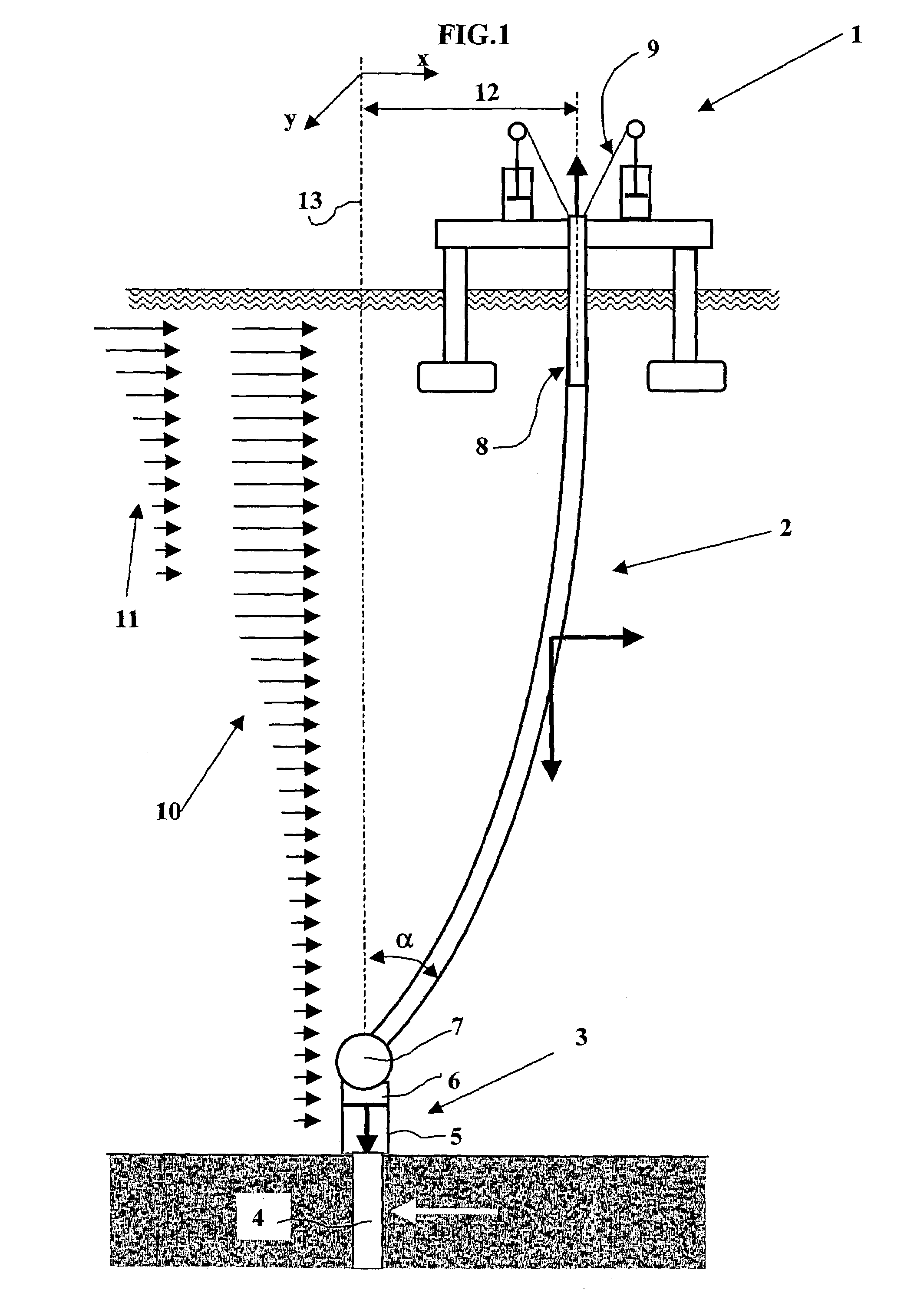
[0017]FIG. 1 shows the global architecture of an offshore drilling installation operated from a floater 1. This type of installation requires a riser 2 consisting of an assembly of elements connected to one another. The riser connects the floater to subsea wellhead 3. Wellhead 3 consists of a conductor pipe 4 sealed in the sea bottom, elements that support safety preventers 5, which comprise an upper part LMRP (Lower Marine Riser Package) 6 that can be separated from the lower part by means of a connector. Upper part LMRP remains suspended from the riser in the disconnected mode. In the connected mode, the base of the riser can be inclined at an angle α by means of knuckle type joint 7. The upper part of riser 2 is fastened to floater 1 by a telescopic joint 8 which allows to take up the vertical displacements due to the waves, and by a system of tensioners 9 generally consisting of cables, pulleys and hydropneumatic jacks that maintain the riser under tension and allow its deflecte...


PUM


Abstract

The present invention relates to an instrumentation assembly intended for an offshore riser (2) operated from a floater (1). It comprises a central processing unit (PC) connected by conducting cables (27) to:
    • a plurality of modules (21–25) fastened to various points of the riser length, the modules comprising measuring means allowing dynamic location of said points in space,
    • another locating module (26) fastened to the lower end (LMRP) of said riser,
    • a series of detectors (W, C, M/W) for measuring the environment: wind, wave, current,
    • an assembly for measuring the position (DGPS, P) of the floater.
The measurements are synchronized with one another, managed and recorded by means of the central processing unit.

Description

FIELD OF THE INVENTION[0001]The present invention relates to the development of deep offshore oil reservoirs, i.e. at water depths above 1000 meters, in particular above 2000 m. To produce such reservoirs, the production well drilling operations require heavy and therefore costly installations, which involves surveys and techniques specific to the local conditions. Industrialists in the profession currently have a certain number of computer programs allowing complex computations to optimize the installations according to specifications. However, at such depths, the problems are such that the computing programs are currently not totally validated for extreme conditions: water depth, wind, current, etc.[0002]The present invention relates to a deep-water drilling installation allowing to control all of the stresses and deformations undergone by the riser considering the oceanographical and operating conditions. What is referred to as control is real-time, pseudo-real time, or not, reco...

Claims


Application Information

Patent Timeline
IPC IPC(8): E21B29/12E21B17/01E21B19/00E21B47/00
CPCE21B17/01E21B47/0001E21B19/002E21B47/001
Inventor GUESNON, JEANVAISBERG, OLIVIERPIGNARD, GUYGUERIN, PIERRE
Owner INST FR DU PETROLE
Why Eureka
Try Eureka