
Vibratory pile driver/extractor with two-stage vibration/tension load suppressor

a technology of vibration/tension load suppressor and vibration/tension load, which is applied in the direction of percussive tools, manufacturing tools, portable drilling machines, etc., can solve the problems of high tension load, damage to supporting cables and hoisting machinery, and time-consuming and labor-intensive problems

Active Publication Date: 2006-07-25
INT CONSTR EQUIP
View PDF27 Cites 40 Cited by
  • Summary
  • Abstract
  • Description
  • Claims
  • Application Information

AI Technical Summary

Benefits of technology

[0016]The present invention also includes a method of absorbing the vibration and tension loads generated by a vibratory unit carried in a housing and connected to a pile for driving and extracting the pile. The method includes the steps of raising and lowering the housing and the vibratory unit using a support; absorbing the vibration generated by the vibratory unit and absorbing the tension load applied by the support utilizing shear strain; and absorbing the vibration generated by the vibratory unit and absorbing the tension load applied by the support using an elastomeric compression element positioned to be compressed between the vibratory unit and the housing whenever the tension load generated by the support exceeds a predetermined level. This method may also include the step of generating an audible sound of metal engaging metal when the compression element positioned between the vibratory unit and the housing is fully compressed by the tension load.

Problems solved by technology

However, during pile extracting operations, the cable must not only bear the dead weight of the housing and vibratory unit, it is also subjected to the high tension loads required to extract the pile from the ground.
Vibration and tension loads generated during the pile extraction operation can damage the supporting cable and hoisting machinery if the vibration and tension loads are not properly absorbed.
This arrangement had the major disadvantage of being both time consuming and labor intensive.
One disadvantage of this arrangement is that during pile driving operations, when there is generally some tension maintained in the cable, the vibration imparted to the cable is not absorbed since the first set of weaker springs maintains the yoke and the vibratory unit in fixed, rigid relation to one another.
Additionally, during pile extracting operations, when the tension load exceeds the level at which the set of stiffer springs come into play, the first set of weaker springs become essentially non-functional and do not supplement the tension absorbing action of the set of stiffer springs.
While these shear members are capable of absorbing loads encountered in conventional pile driving and pile extracting rigs, each member has a somewhat limited vibration and tension load absorbing capacity, and therefore in instances where the tension loads are very high, the number of vibration / tension load absorbing elements must be increased, all of which can increase the expense of the rig and the size of rig that must accommodate the increased number of shear members.

Method used


Image

  • Vibratory pile driver/extractor with two-stage vibration/tension load suppressor
  • Vibratory pile driver/extractor with two-stage vibration/tension load suppressor
  • Vibratory pile driver/extractor with two-stage vibration/tension load suppressor

Examples


Embodiment Construction

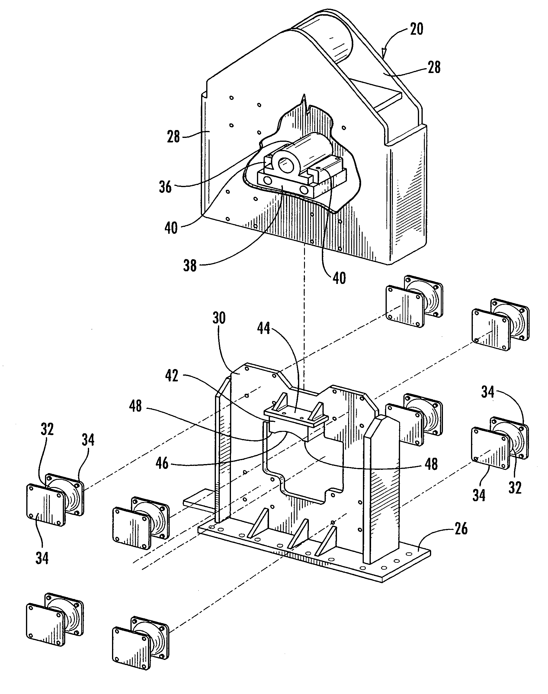
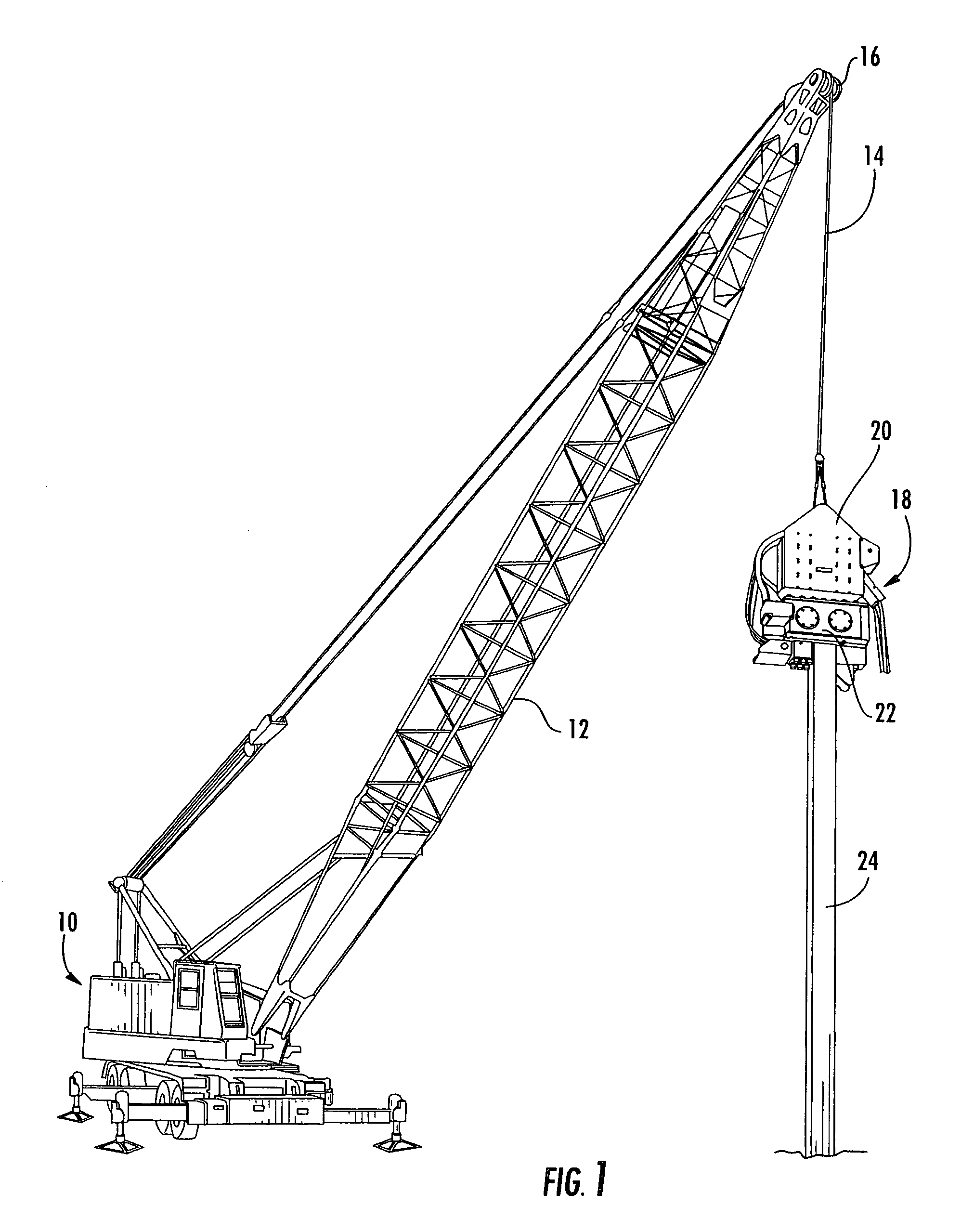
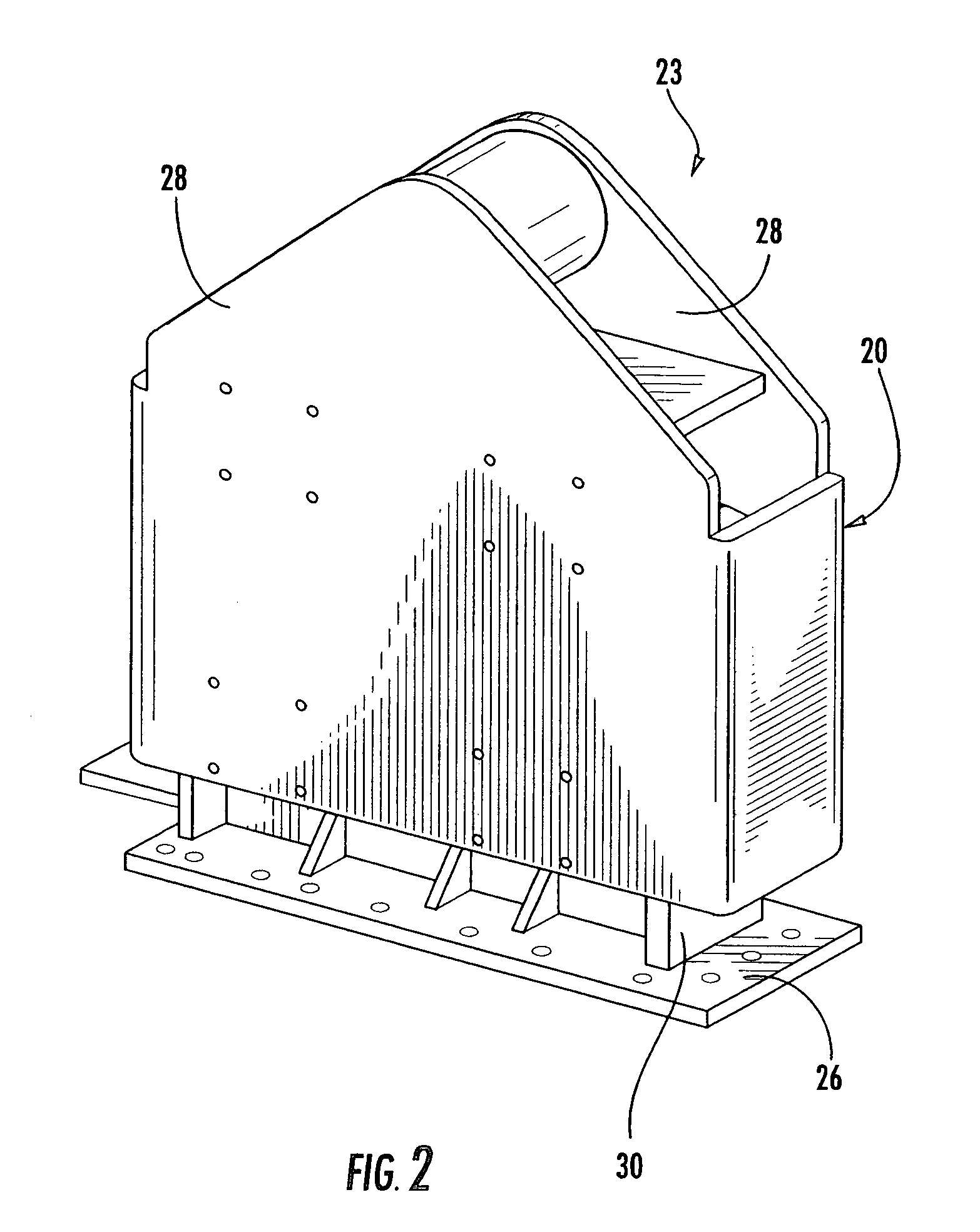
[0027]Looking now in greater detail at the accompanying drawings, FIG. 1 illustrates a typical pile driving and extracting rig with which the vibration / tension load absorbing features of the present invention may be utilized. This rig includes a crane 10 having a boom 12 that is pivotally mounted on the crane 10. A support cable 14 extends upwardly through the boom 12 and over a pulley 16 at the top of the boom 12, and the end of the cable 14 supports a vibratory pile driver / extractor 18. The vibratory pile driver / extractor 18 includes a housing 20, and a vibrator 22 which is mounted within the housing 20 in a manner to be described in greater detail below.

[0028]In operation, the crane 10 manipulates the vibratory pile driver / extractor 18 over a pile 24 so that the vibrator 22 can engage the upper end of the pile 24 as illustrated in FIG. 1. The cable 14 is then extended or retracted to raise or lower the vibratory pile driver / extractor 18, depending on whether the pile 24 is being ...


PUM

PropertyMeasurementUnit
tension forceaaaaaaaaaa
vibratory forceaaaaaaaaaa
tensionaaaaaaaaaa

Abstract

A method and apparatus for driving and extracting piles that includes a vibration / tension load absorber assembly mounted between a housing and the vibratory unit which includes shear-type vibration absorbers connected between the housing and the vibratory unit and operating in combination with at least one compression-type vibration absorber positioned to be compressed between first and second compression plates when the tension load reaches a predetermined level.

Description

BACKGROUND OF THE PRESENT INVENTION[0001]The present invention relates generally to devices or rigs for driving piles and the like into the ground and for extracting piles that have been driven into the ground, and more particularly to rigs of this type that are provided with a vibration / tension load suppressor for absorbing vibration and tension loads generated by the driving and extracting operations.[0002]Vibratory pile driver / extractors which are used for driving and extracting piles and the like generally include a vibratory unit that is connected to a housing which in turn is connected to a cable or other support that lowers and lifts the housing and vibratory unit during the driving and extracting operations, respectively. The vibratory unit is connected to the pile and usually includes rotating eccentrics that impart vibrations to the pile to assist in driving and extracting the pile.[0003]During driving operations, the housing and vibratory unit are positioned on top of the...

Claims


Application Information

Patent Timeline
Patent Type & Authority Patents(United States)
IPC IPC(8): E02D7/18
CPCE02D7/18E02D13/02E02D11/00E02D9/02
Inventor MORRIS, T. RICHARD
Owner INT CONSTR EQUIP
Learn More