Optical head with defocusing correction and spherical aberration correction
Inactive Publication Date: 2006-08-01
PANASONIC CORP
View PDF23 Cites 9 Cited by
Summary
Abstract
Description
Claims
Application Information
AI Technical Summary
This helps you quickly interpret patents by identifying the three key elements:
Problems solved by technology
Method used
Benefits of technology
Benefits of technology
[0005]It is an object of the present invention to solve the conventional problem described above by providing an optical head that is capable of obtaining excellent optical characteristics according to its configuration in which both defocusing correction means and spherical aberration correction means and provided. Thus, while defocusing of a focused spot on an information recording medium caused by a wavelength broadening of a light source and chromatic aberration of an objective lens can be corrected, spherical aberration of the optical system caused by wavelength difference between a design wavelength and an incident wavelength also can be corrected, and furthermore, if necessary, spherical aberration caused by an error in a standard thickness of a base material of the information recording medium can be corrected.
[0006]In order to achieve the above object, the optical head of the present invention includes a light source, an objective lens for focusing a light beam emitted from the light source on an information recording medium and a photodetector for detecting the light beam reflected from the information recording medium, wherein defocusing correction means and spherical aberration correction means are provided in an optical path between the light source and the information recording medium. In the optical head described above, according to the configuration in which both the defocusing correction means and the spherical aberration correction means are provided, while defocusing of a focused spot on the information recording medium caused by a wavelength broadening of the light source and chromatic aberration of the objective lens can be corrected, spherical aberration of the optical system caused by wavelength difference between a design wavelength and an incident wavelength also can be corrected, and furthermore, if necessary, spherical aberration caused by an error in a standard thickness of a base material of the information recording medium can be corrected. As a result, excellent optical characteristics can be obtained.
[0007]In the optical head described above, the light source preferably has a wavelength broadening in which a full width at half maximum of a wavelength is substantially 0.3 nm or more. When the light source has a wavelength broadening of such a range, defocusing is likely to occur on the information recording medium, thereby degrading the focused spot. Therefore, the effect of the present invention is more significant.
Problems solved by technology
When the wavelength is within such a range, the occurrence of defocusing and the amount of spherical aberration caused by the wavelength deviation is increased even more, and signals on the information recording medium may not be read out easily.
Method used
Image
Click on the blue label to locate the original text in one second.
Reading with bidirectional positioning of images and text.
Examples
embodiment 1
[0052]First, an optical head according to Embodiment 1 of the present invention will be explained in detail by using FIG. 1 to FIG. 5 and by determining the coordinate axis as illustrated in each drawing.
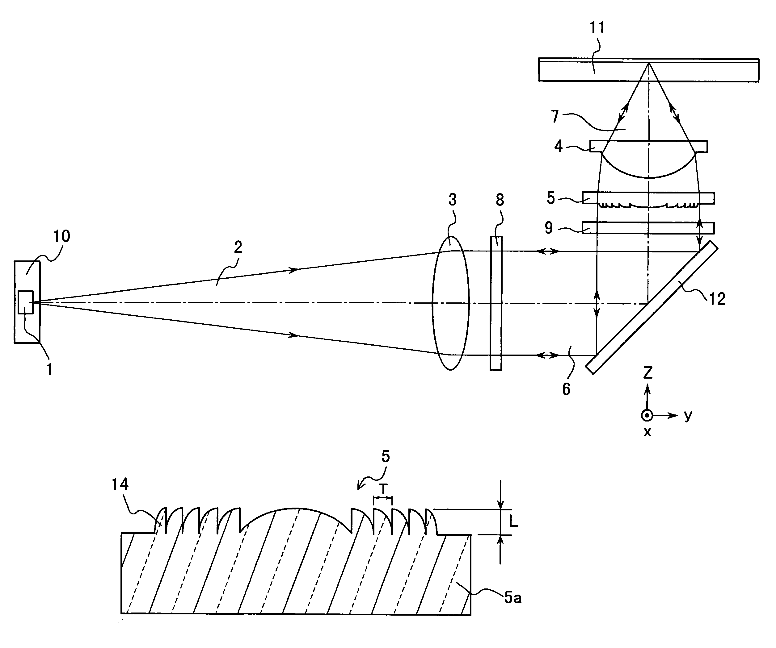
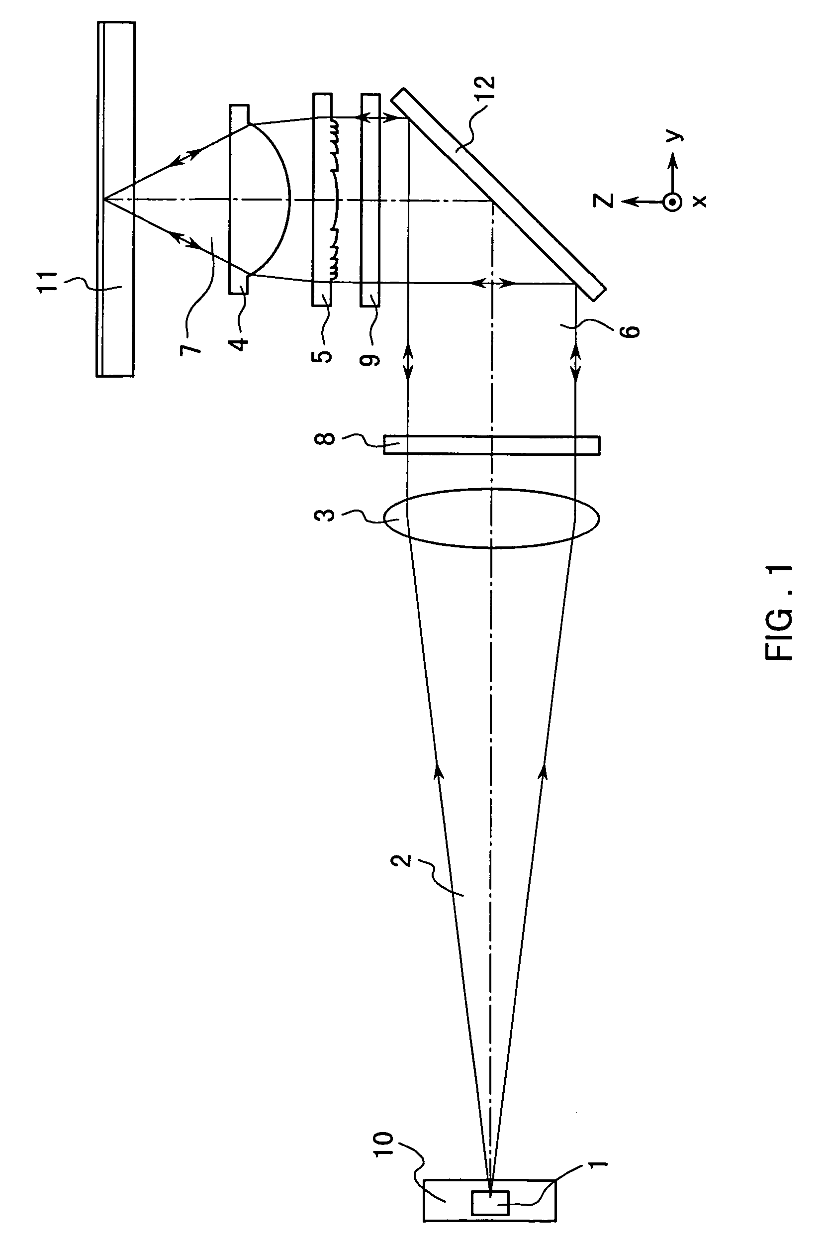
[0053]FIG. 1 is a side view showing the basic structure of the optical head according to Embodiment 1 of the present invention and how a light beam is propagated.
[0054]As illustrated in FIG. 1, on an optical path from a light source 1 to an information recording medium 11, which is an optical disc such as DVD, CD etc., an objective lens 4, a defocusing correction element 5 as defocusing correction means, a spherical aberration correction element 9 as spherical aberration correction means, a mirror 12, a focus / tracking errorsignal detecting element 8 and a collimator lens 3 are arranged.
[0055]The light source 1 is a light source having a substantially wavelength broadening. This light source 1 is, for example, a light source with a wavelength of 405 nm, which is integrated together ...
embodiment 2
[0083]Next, an optical head in Embodiment 2 of the present invention will be explained with reference to FIG. 6 by mainly referring to the point that is different from Embodiment 1 described above. FIG. 6 is a side view showing the basic structure of the optical head according to Embodiment 2 of the present invention and how a light beam is propagated.
[0084]According to the configuration of the optical head in the present embodiment, the defocusing correction element 5a, which is defocusing correction means, and the spherical aberration correction element 9a, which is spherical aberration correction means, are integrated. By forming the defocusing correction element 5a on top of the spherical aberration correction element 9a, the defocusing correction means and the spherical aberration correction means can be formed as one component. As a result, a thinner device can be manufactured, and position adjustment is no longer necessary.
[0085]Furthermore, the defocusing correction element ...
embodiment 3
[0086]Next, an optical head according to Embodiment 3 will be explained with reference to FIGS. 7, 8 by mainly referring to the point that is different from Embodiment 1 described above. FIG. 7 is a side view showing the basic structure of the optical head according to Embodiment 3 and how a light beam is propagated. FIG. 8(b) is a plan view of an objective lens with a defocusing correction element formed according to Embodiment 3, and FIG. 8(a) is a cross-sectional view taken on line II—II of FIG. 8(b).
[0087]As illustrated in FIG. 8, a concentric circular pattern is formed on an objective lens 4a. This pattern has, as illustrated in FIG. 8(a), a cross-section substantially of a saw-tooth shape having a step s, and a defocusing correction element 5b is formed by this saw-tooth shape. By integrating the defocusing correction element 5b with the objective lens 4a, the optical head can be miniaturized, and position adjustment also can be simplified.
[0088]Here, the step s is formed to s...
PUM
Abstract
An optical head with excellent optical characteristics even when using a light source that substantially has a wavelength broadening is provided. The optical head includes a light source, an objective lens for focusing a light beam emitted from the light source on an information recording medium and a photodetector for detecting the light beam reflected from the information recording medium, wherein defocusing correction means and spherical aberration correction means are provided in an optical path between the light source and the information recording medium. Since both the defocusing correction means and the spherical aberration correction means are provided, while defocusing of a focused spot on the information recording medium caused by a wavelength broadening of the light source and chromatic aberration of the optical system can be corrected, the spherical aberration of the optical system caused by wavelength difference between a design wavelength and an incident wavelength also can be corrected. As a result, excellent optical characteristics can be obtained.
Description
FIELD OF THE INVENTION[0001]The present invention relates to an optical head used for an optical recording / reproduction device. In particular, the present invention relates to an optical head with excellent optical characteristics even when using a light source that substantially has a wavelength broadening.BACKGROUND OF THE INVENTION[0002]As an important component part for reading out signals from optical recording media such as optical discs, e.g. compact discs (CD), DVD etc., optical card memories or the like, an optical head is available. In order to take out signals from the optical recording media, the optical head needs to be equipped not only with a signal detection function but also with a control mechanism such as a focusing servo, a tracking servo and the like.[0003]The optical head usually includes various optical components such as a light source, a photodetector, an objective lens, a focus / tracking errorsignal detecting element, a mirror, a collimator lens etc. A lase...
Claims
Application Information
Patent Timeline
Application Date:The date an application was filed.
Publication Date:The date a patent or application was officially published.
First Publication Date:The earliest publication date of a patent with the same application number.
Issue Date:Publication date of the patent grant document.
PCT Entry Date:The Entry date of PCT National Phase.
Estimated Expiry Date:The statutory expiry date of a patent right according to the Patent Law, and it is the longest term of protection that the patent right can achieve without the termination of the patent right due to other reasons(Term extension factor has been taken into account ).
Invalid Date:Actual expiry date is based on effective date or publication date of legal transaction data of invalid patent.

