Optical scanning system

a scanning system and optical technology, applied in the field of optical scanning systems, can solve the problems of deterioration of quality of drawing, high cost, and large space requirements of long-length imaging lenses, and achieve the effect of increasing the spot diameter

Active Publication Date: 2017-01-17
NALUX CO LTD
View PDF14 Cites 0 Cited by
  • Summary
  • Abstract
  • Description
  • Claims
  • Application Information

AI Technical Summary

Benefits of technology

[0016]Since Expression (1) is satisfied in the present invention, the numerical aperture at each end of the scanning line can be made greater than the numerical aperture at the center of the scanning line. Accordingly, an increase in the spot diameter at each end of the scanning line, which is caused by an obliquely incident beam, can be balanced with the increase in the numerical aperture.
[0021]Since Expression (5) is satisfied in the present embodiment, a ratio of the numerical aperture at each end of the scanning line to the numerical aperture at the center of the scanning line can be appropriately determined.
[0025]Since Expression (6) is satisfied in the present embodiment, the numerical aperture at each end of the scanning line increases, and therefore an increase in the spot diameter at each end of the scanning line, which is caused by an oblique incident beam with an incidence angle of φ, can be balanced with the increase in the numerical aperture. As a result, variation in the spot diameter across the scanning line can be made smaller than 5%.
[0027]In the present embodiment, by the use of the condenser lens that is configured to move in the direction of the optical axis such that the beam forms an image on the light receiving surface, an increase in the spot diameter at each end of the scanning line, which is caused by an obliquely incident beam, can be balanced.

Problems solved by technology

However, the long-length imaging lens is not only expensive, but also requires a larger space for arrangement, and therefore an apparatus containing the scanning optical system is upsized.
As a result, the spot diameter ω′ at the image point at each end of the scanning line is greater than the spot diameter ω at the image point at the center of the scanning line, and therefore quality of drawing will deteriorate.
In this conventional optical system, however, a variable-focus optical system in which a number of fixed-focus lenses and a number of variable-focus lens are combined besides the imaging lens is employed, and therefore the optical system requires a relatively complicated structure and high costs.
However, in this case, the focal length of the fixed-focus lenses becomes greater, and the distance between the variable-focus lens system and the fixed-focus lens system has to be increased.

Method used


Image

  • Optical scanning system
  • Optical scanning system
  • Optical scanning system

Examples


example 1

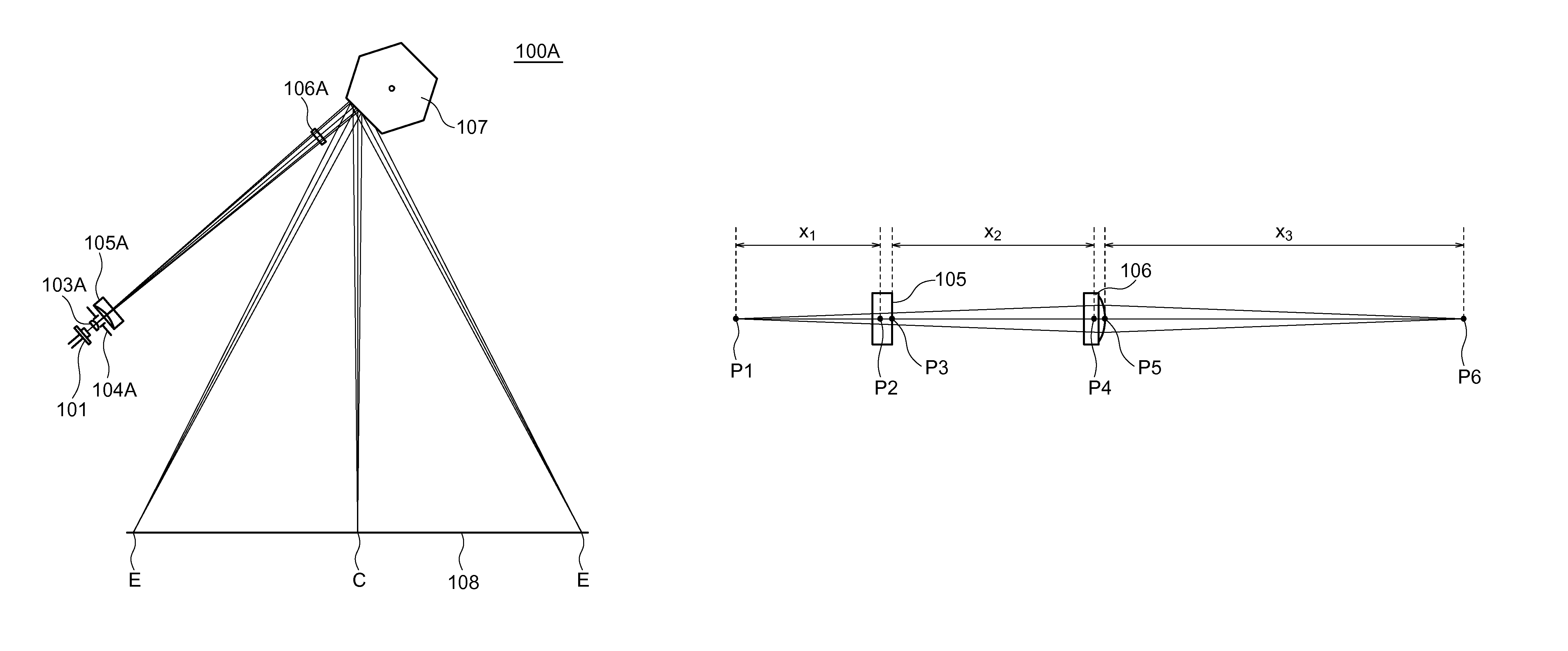
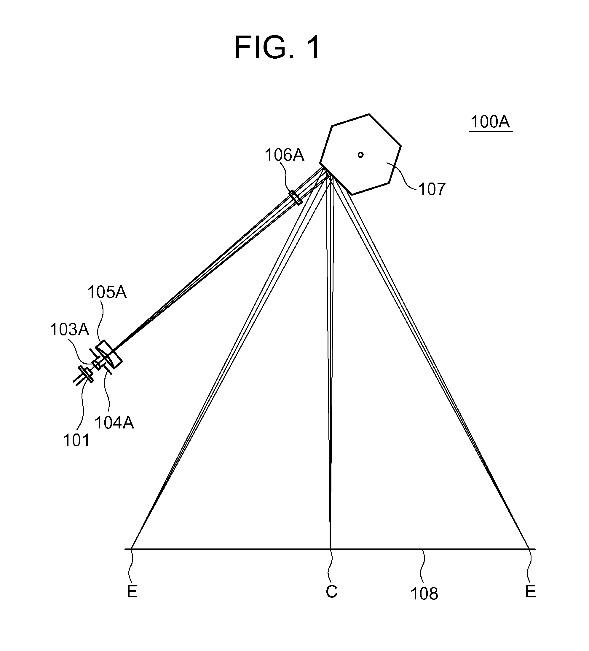
[0071]FIG. 1 shows an arrangement of the optical scanning system 100A of Example 1. The optical scanning system 100A includes the condenser lens 103A, the aperture 104A, the variable-focus element 105A, the imaging lens 106A and the deflector 107 such as a polygon mirror. Light emitted by the laser diode light source 101, wavelength of which is 780 nm, is converted into a predetermined divergent beam by the condenser lens 103A, made to pass through the variable-focus element 105A and the imaging lens 106A and deflected by the deflector 107 such that the beam scans a light receiving surface 108 in the horizontal direction in FIG. 1. The variable-focus element 105A is controlled such that the beam constantly forms an image on the light receiving surface during the period of the scanning. In FIG. 1, the center of the scanning line on the light receiving surface 108 is represented as C and the both ends are represented as E.

[0072]Table 1 shows numerical data of the optical scanning syst...

example 2

[0081]FIG. 4 shows an arrangement of an optical scanning system 100B of Example 2. The optical scanning system 100B includes a condenser lens 103 B, an aperture 104B, an imaging lens 106B and a deflector 107 such as a polygon mirror. Light emitted by a laser diode light source 101, wavelength of which is 780 nm, is converted into a predetermined divergent beam by the condenser lens 103B, made to pass through the imaging lens 106B and deflected by the deflector 107 such that the beam scans a light receiving surface 108 in the horizontal direction in FIG. 4. The condenser lens 103B is made to move in the direction of the optical axis in a predetermined section in synchronization with the scanning caused by the deflector 107. Movement of the condenser lens 103B in the direction of the optical axis changes a position of an image of the beam along the optical path. The position of the condenser lens 103B is controlled such that the beam constantly forms an image on the light receiving su...

example 3

[0089]FIG. 5 shows an arrangement of an optical scanning system 100C of Example 3. The optical scanning system 100C includes a condenser lens 103C, an aperture 104C, a variable-focus element 105C, an imaging lens 106C and a deflector 107 such as a polygon mirror. Light emitted by a laser diode light source 101, wavelength of which is 780 nm, is converted into a predetermined divergent beam by the condenser lens 103C, made to pass through the variable-focus element 105C and deflected by the deflector 107 such that the beam scans a light receiving surface 108 in the horizontal direction in FIG. 5. Then, the beam passes through the imaging lens 106C. The variable-focus element 105C is controlled such that the beam constantly forms an image on the light receiving surface during the period of the scanning. In FIG. 5, the center of the scanning line on the light receiving surface 108 is represented as C and the both ends are represented as E.

[0090]Table 5 shows numerical data of the optic...


PUM


Abstract

An optical scanning system includes a variable-focus element, an imaging lens and a deflector, wherein the reciprocal of the focal length f of the variable-focus element is changed from 1 / fMIN to 1 / fMAX, and for the case that the equation1 / f={(1 / fMAX)+(1 / fMIN)} / 2holds, a beam which has passed through the variable-focus element is a divergent beam, andx2+x22x1>x3(1)is satisfied, where x1 represents a distance from a virtual image point of the divergent beam to the principal point on the entry side of the variable-focus element, x2 represents a distance from the principal point on the exit side of the variable-focus element to the principal point on the entry side of the imaging lens, and x3 represents a distance from the principal point on the exit side of the imaging lens to an image point.

Description

TECHNICAL FIELD[0001]The present invention relates to an optical scanning system which uses a variable-focus element.BACKGROUND ART[0002]In the measuring mechanism or the drawing mechanism of a laser printer, an optical scanning system is employed. The optical scanning system makes a beam emitted by a light source such as a laser diode pass through a condenser lens, deflects the beam by a deflector such as a polygon mirror or a swing mirror, and makes the beam form an image on the image plane of the scanning beam. In the optical scanning system for a laser printer, for example, it is important to keep the beam spot diameter constant for the whole scanned area (along the whole length of the scanning line).[0003]Conventionally, in order to realize a constant beam spot diameter along the whole length of the scanning line, a long-length imaging lens is commonly arranged between the deflector and the image plane. However, the long-length imaging lens is not only expensive, but also requi...

Claims


Application Information

Patent Timeline
Patent Type & Authority Patents(United States)
IPC IPC(8): G02B26/08G02B26/12G02B3/14
CPCG02B26/128G02B3/14G02B26/12G02B26/124
Inventor SEKI, DAISUKESUZUKI, TAKATOSHIKUWAGAITO, TOMOHITO
Owner NALUX CO LTD
Why Eureka
Try Eureka