Diffraction element and optical disk device

a technology of optical disk and diffraction element, which is applied in the field of diffraction element and optical disk device, can solve the problem of properly obtaining the tracking error signal

Inactive Publication Date: 2006-09-28
SANKYO SEIKI MFG CO LTD
View PDF5 Cites 0 Cited by
  • Summary
  • Abstract
  • Description
  • Claims
  • Application Information

AI Technical Summary

Benefits of technology

[0008] In view of the problems described above, an embodiment of the present invention may advantageously provide a diffraction element which is capable of improving the degree of freedom of the “NA” numerical aperture and the optical magnification by being capable of setting the spot shape and the diffraction efficiency in desired conditions, and may advantageously provide an optical disk device which utilizes the diffraction element.
[0011] In accordance with an embodiment, since the depth dimension of the groove part of the diffraction element varies according to position, the spot shape and the diffraction efficiency can be set in desired conditions and the degree of freedom of the degree of aperture and the optical magnification can be improved. For example, in the case that the diffraction element to which the present invention is applied is used as a three-beam generating element in an optical disk device, when a main beam comprised of a 0-order light beam and sub-beams comprised of diffracted light beams are formed from a laser beam emitted from a laser light source, the groove part of the diffraction element is formed such that the depth dimension between the upper faces of the protruded parts on both sides of the groove part and the bottom part of the groove part varies according to position. Therefore, when the light beam is passed through the diffraction element, since a part of the light beam is diffracted in comparison with the light beam before passing through the diffraction element, and thus the peak shape of the zero-order light beam becomes, for example, to be the shape that the level of the lower slope portion is raised by the quantity of decreasing in the center region. Accordingly, with respect to the zero-order light beam which is incident on an objective lens, a similar effect as when “NA” numerical aperture is increased can be obtained, and thus the spot diameter of a main beam can be made smaller when the main beam is converged on the track of an optical disk. As described above, the spot shape and the diffraction efficiency can be set in desired conditions and thus the degree of freedom of the degree of aperture and the optical magnification can be improved. Further, the duty ratio of a grating in the diffraction element may be set to be 50:50 and thus the generation of high-order diffraction light beams can be restrained. Therefore, the spot diameters of the sub-beams which are converged on an optical disk are enlarged. Accordingly, since the tolerance of positional accuracy between a track and the sub-beams becomes wider, working efficiency can be improved when an optical disk device is manufactured. Further, even in optical disks with different track pitches, a tracking error signal can be obtained properly.
[0014] In accordance with an embodiment, the center position in the depth direction of the groove part may be set to be the same height position in the longitudinal direction of the groove part. According to the structure described above, the generation of astigmatism due to the diffraction element can be prevented.
[0016] In accordance with an embodiment, the center positions in the depth direction of a plurality of the groove parts may be set to be the same height position. According to the structure described above, the generation of astigmatism due to the diffraction element can be prevented.

Problems solved by technology

Further, even in optical disks with different track pitches, a tracking error signal can be obtained properly.

Method used


Image

  • Diffraction element and optical disk device
  • Diffraction element and optical disk device
  • Diffraction element and optical disk device

Examples


first embodiment

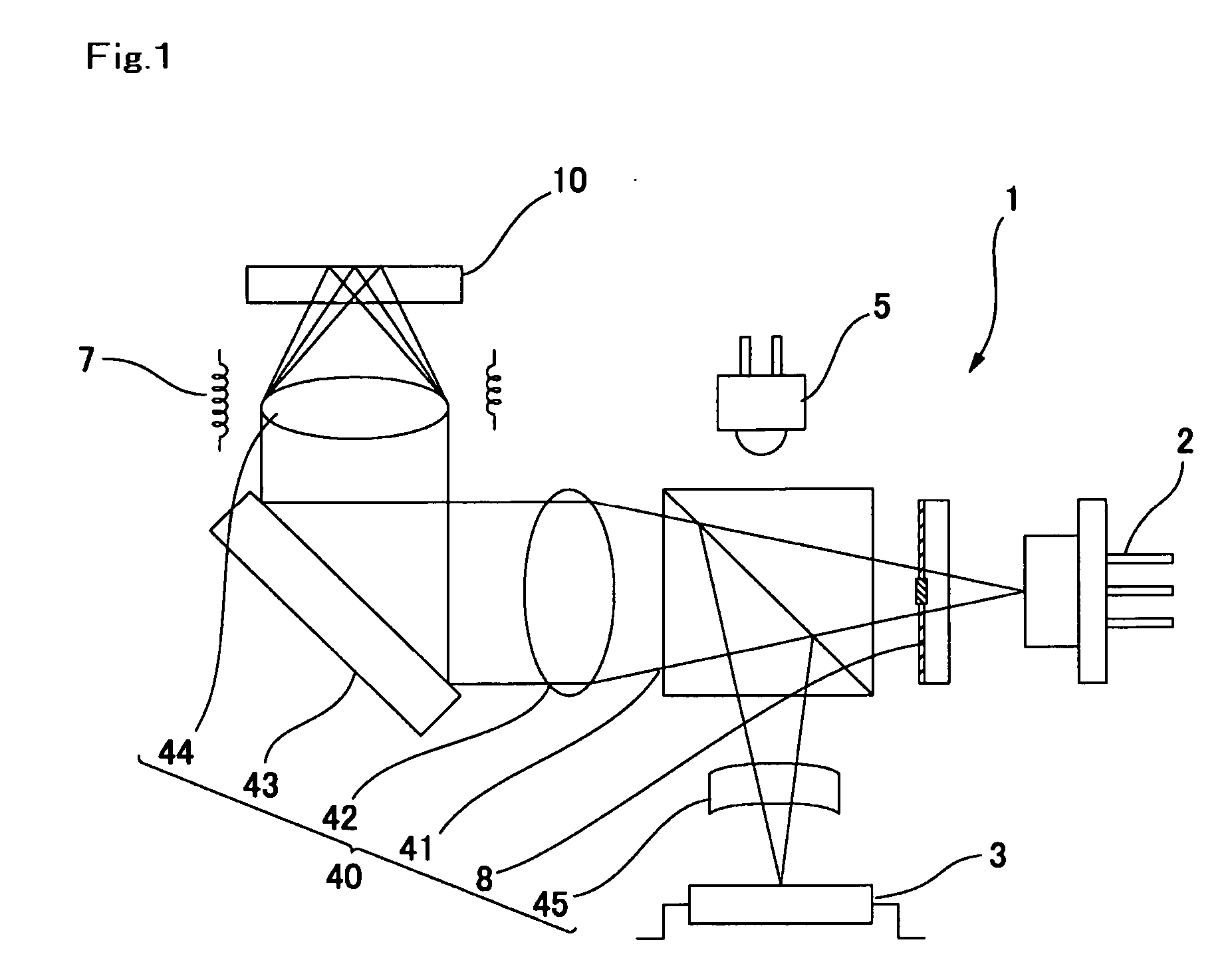
[0031]FIG. 1 is an explanatory view showing a schematic structure of an optical disk device in accordance with a first embodiment of the present invention.

[0032] In FIG. 1, an optical disk device 1 in accordance with the first embodiment includes a semiconductor laser 2 for emitting a laser light beam with, for example, the wavelength of 650 nm and a photo-detector 3. Further, the optical disk device 1 includes a beam splitter 41, a collimating lens 42, a rising mirror 43 and an optical system 40 provided with an objective lens 44 from the semiconductor laser 2 to an optical recording disk 10. A forward path through which the laser beam emitted from the semiconductor laser 2 is guided to the optical recording disk 10 is structured by these optical elements. Further, the optical system 40 is provided with a sensor lens 45 between the beam splitter 41 and the photo-detector 3. A return path through which the return light beam reflected by the optical disk 10 is guided to the photo-de...

second embodiment

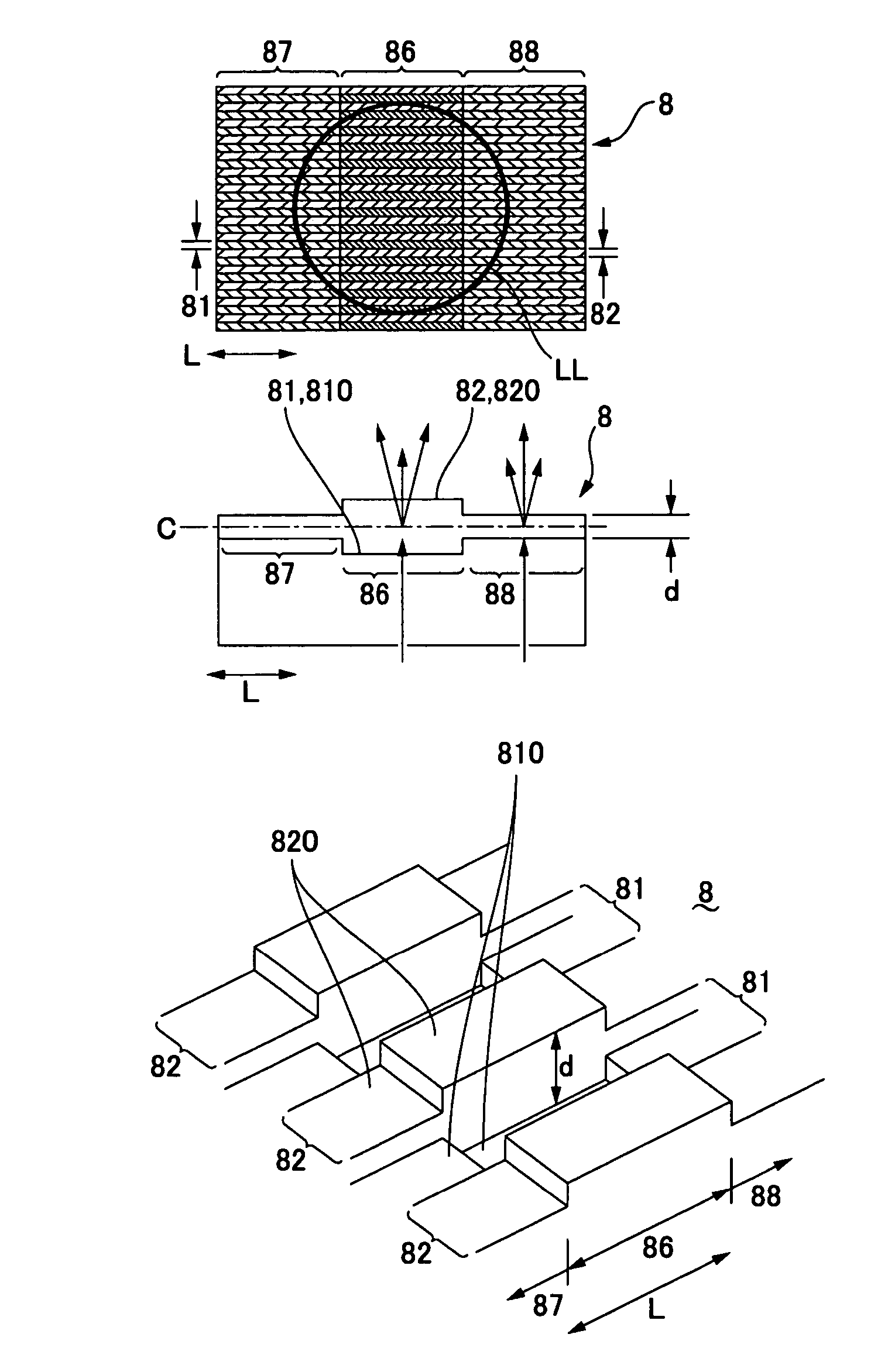
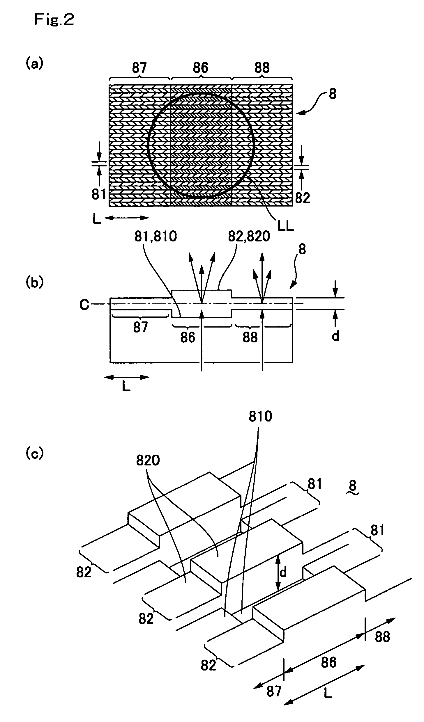
[0044]FIG. 5(a) is a plan view showing a diffraction element which is used in a second embodiment of the present invention, FIG. 5(b) is a sectional view showing the diffraction element which is cut along the longitudinal direction of a groove part, and FIG. 5(c) is its perspective view. The basic structures in the second, a third and a fourth embodiments described below are common to the first embodiment and thus the same notational symbols are used in the common portions.

[0045] As shown in FIGS. 5(a), 5(b) and 5(c), also in the optical disk device 1 in accordance with a second embodiment, similarly to the first embodiment, the depth dimension “d” between the upper faces 820 of the protruded parts 82 on both sides of the groove part 81 and the bottom part 810 of the groove part 81 varies according to the position in all the groove parts 81 of the diffraction element 8.

[0046] In the second embodiment, similarly to the first embodiment, the depth dimension “d” in all groove parts 8...

third embodiment

[0051]FIG. 6(a) is a plan view showing a diffraction element which is used in a third embodiment of the present invention, FIG. 6(b) is a sectional view showing the diffraction element which is cut along the longitudinal direction of a groove part, and FIG. 6(c) is its perspective view.

[0052] As shown in FIGS. 6(a), 6(b) and 6(c), also in the optical disk device 1 in accordance with a third embodiment, similarly to the first embodiment, the depth dimension “d” between the upper faces 820 of the protruded parts 82 on both sides of the groove part 81 and the bottom part 810 of the groove part 81 varies according to the position in all the groove parts 81 of the diffraction element 8. In other words, in all groove parts 81, the bottom part 810 is formed in a curved shape such that its center portion in the longitudinal direction is concaved and the upper faces 820 of all the protruded parts 82 are formed in a flat face. Therefore, in the center region 86 in the longitudinal direction ...


PUM


Abstract

A diffraction element includes a plurality of groove parts and a plurality of protruded parts which are alternately arranged with a plurality of the groove parts. The depth dimension between the upper faces of the protruded parts on both sides of the groove part and the bottom part of the groove part varies according to position. The diffraction element may be preferably disposed at a middle position of a forward path as a three-beam generating element that generates a main beam comprised of a 0-order light beam and two sub-beams comprised of diffracted light beams from a laser beam emitted from a laser light source.

Description

CROSS REFERENCE TO RELATED APPLICATION [0001] The present invention claims priority under 35 U.S.C. §119 to Japanese Application No. 2005-86981 filed Mar. 24, 2005 which is incorporated herein by reference. FIELD OF THE INVENTION [0002] An embodiment of the present invention may relate to a diffraction element in which groove parts and projection parts are alternately arranged and may relate to an optical disk device provided with the diffraction element. BACKGROUND OF THE INVENTION [0003] Various structures have been proposed to perform recording or reproduction of information on or from an optical disk. Even when various structures are utilized, an optical disk device commonly includes a laser light source, a photo-detector, and an optical system which structures a forward path for guiding a laser beam emitted from a laser light source to an optical disk and a return path for guiding a return light beam reflected by the optical disk to the photo-detector. Further, various diffract...

Claims


Application Information

Patent Timeline
IPC IPC(8): G11B7/135
CPCG02B5/1861G11B7/1353
Inventor SAKAI, HIROSHI
Owner SANKYO SEIKI MFG CO LTD
Why Eureka
Try Eureka