Optical system, method and laser imaging device capable of adjusting spot diameter

A technology of optical system and spot diameter, applied in the field of optics, can solve the problem that the diameter of the spot cannot be reduced, and the image resolution cannot be improved, so as to achieve the effect of improving the image resolution and improving the resolution.

Active Publication Date: 2021-12-14
深圳市先地图像科技有限公司
View PDF0 Cites 0 Cited by
  • Summary
  • Abstract
  • Description
  • Claims
  • Application Information

AI Technical Summary

Problems solved by technology

[0003] The invention provides an optical system capable of adjusting the diameter of the spot, and its purpose is to so

Method used


Image

  • Optical system, method and laser imaging device capable of adjusting spot diameter
  • Optical system, method and laser imaging device capable of adjusting spot diameter
  • Optical system, method and laser imaging device capable of adjusting spot diameter

Examples


Embodiment 1

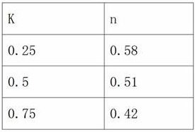
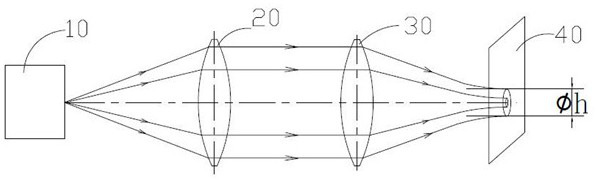
[0042] refer to Figure 4 , Figure 4 It is an embodiment diagram of the optical path structure schematic diagram of the present invention, that is, the ring light generating module is a ring light output module 12, and the ring light output module 12 emits a hollow ring light beam. As one of the embodiments, the ring light output module 12 can be as follows Figure 10 The shown ring-shaped light-emitting light source is composed of several light-emitting units 80, and the ring-shaped light-emitting source emits a hollow ring-shaped light beam. The hollow ring light beam is incident on the imaging lens 60 to form ring light. It can be understood that, in this embodiment, the size of the ring-shaped light-emitting area of ​​the ring-shaped light-emitting module can be adjusted, so that the value of b can be adjusted to achieve the purpose of reducing r.

Embodiment 2

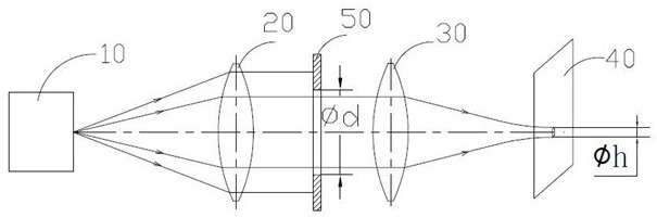
[0044] In this embodiment, the ring light generation module consists of Figure 5 It is composed of the point light source 13 and the circular light blocking sheet 14 arranged between the point light source 13 and the imaging lens 60. It can be understood that, after the conical light beam emitted by the point light source 13 is blocked by the circular light blocking sheet 14, Ring light is formed on the imaging lens 60 . Due to the existence of the circular light blocking sheet 14 , the peripheral part of the conical light beam emitted by the point light source 13 can enter the imaging lens 60 , and after being transmitted and focused by the imaging lens 60 , it is focused and imaged on the focal plane 40 . The middle part of the conical light beam emitted by the point light source 13 cannot pass through the imaging lens 60 and focus on the focal plane 40 because it is blocked by the circular light blocking plate 14 . After being blocked by the circular light-blocking sheet ...


PUM


Abstract

The invention discloses an optical system capable of adjusting the diameter of the light spot. The optical system includes: an annular light generating module, an imaging lens and a focusing plane sequentially arranged on the optical axis; the annular light generating module emits a hollow annular light beam to form an annular light on the imaging lens , after the ring light is transmitted through the imaging lens, it forms a diffraction pattern on the focal plane; define the wavelength of the light source as λ, the focal length of the imaging lens as f, the outer diameter of the imaging lens as a, and the inner diameter of the ring light as b, b= k×a, k∈(0,1), is a variable coefficient value, the value of the radius of the circular bright spot at the center of the diffraction pattern obtained by the luminous light source on the focal plane is:, n is the value that decreases with the increase of k Small second variable value. The invention also discloses a method for adjusting the spot diameter by using an optical system and a laser imaging device including the optical system. The invention can reduce the diameter of the light spot, improve the imaging resolution, and reduce the difficulty of the manufacturing process of the imaging lens.

Description

technical field [0001] The invention belongs to the field of optics, and in particular relates to an optical system, a method and a laser imaging device capable of adjusting the spot diameter. Background technique [0002] refer to figure 1 After being collimated by the collimating mirror 20, the light emitted by the light emitting source 10 is emitted to the focusing lens 30 in parallel, and after being focused by the focusing lens 30, it converges on the imaging surface 40 to form a spot with a diameter of h. In order to reduce the value of the spot diameter, that is, in order to make the value of the spot diameter h smaller, the common practice in the prior art is to insert a ring light with an adjustable inner diameter d on the optical path between the collimating mirror 20 and the focusing lens 30 Appendices 50. The size of the spot diameter h can be changed by adjusting the size of the inner diameter d of the annular diaphragm 50 . However, in fact, no matter how th...

Claims


Application Information

Patent Timeline
IPC IPC(8): G02B27/09
CPCG02B27/0955
Inventor 陈乃奇张向非
Owner 深圳市先地图像科技有限公司
Why Eureka
Try Eureka