Light profile microscopy apparatus and method

a microscopy and light-emitting technology, applied in the field of light-emitting microscopy, can solve the problems of severe limitation and far from the diffraction limit of image resolution, and achieve the effect of wide image field and high image resolution

Inactive Publication Date: 2009-05-26
POWER JOAN F
View PDF7 Cites 31 Cited by
  • Summary
  • Abstract
  • Description
  • Claims
  • Application Information

AI Technical Summary

Benefits of technology

[0011]More specifically, there is provided an apparatus for illuminating a test material in a light profile microscope, comprising a source of radiation providing a source beam propagating along a beam axis ‘x’; an anamorphic optical means providing, from the source beam emitted by the source of radiation, a source beam elliptically collimated over an ‘x’ axial collimation region having a distance comprised in a range between micrometers and meters, and having a major elliptic axis oriented along a first transverse axis ‘y’, and a minor elliptic axis oriented along a second transverse axis ‘z’; a test material positioned to intersect the elliptically collimated source beam within the ‘x’ axial collimation region to form an irradiated volume, the test material comprising an image transfer (IT) surface oriented substantially parallel to the ‘x’ axis and substantially orthogonal to the ‘z’ axis, the IT surface transmitting radiation emitted from the irradiated volume in the test material; an optical imaging system (OIS) forming an image, at an image plane, of the illuminated volume in the test material from the radiation transmitted by the IT surface; the OIS defining an object plane conjugate to the image plane and aligned to contain the major elliptic axis ‘y’ of the collimated source beam intersecting the test material in the illuminated volume, an object depth of focus of the OIS being maintained at a value of approximately at least ⅕ of a radius of the elliptically collimated source beam along the ‘z’ axis in the axial collimation region of the elliptically collimated source beam; and image receiving means receiving the image formed by the OIS in the image plane thereof; wherein the apparatus yields a high image resolution and wide image field.

Problems solved by technology

The latter systems have image resolution that is far from the diffraction limit and is limited severely either by optical aberrations or by the dimensions of the image pixels of a camera or image recording instrument.

Method used


Image

  • Light profile microscopy apparatus and method
  • Light profile microscopy apparatus and method
  • Light profile microscopy apparatus and method

Examples


Embodiment Construction

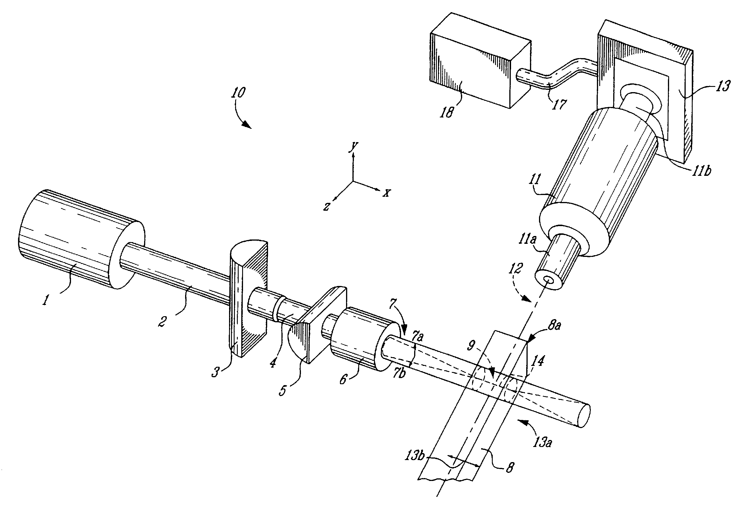
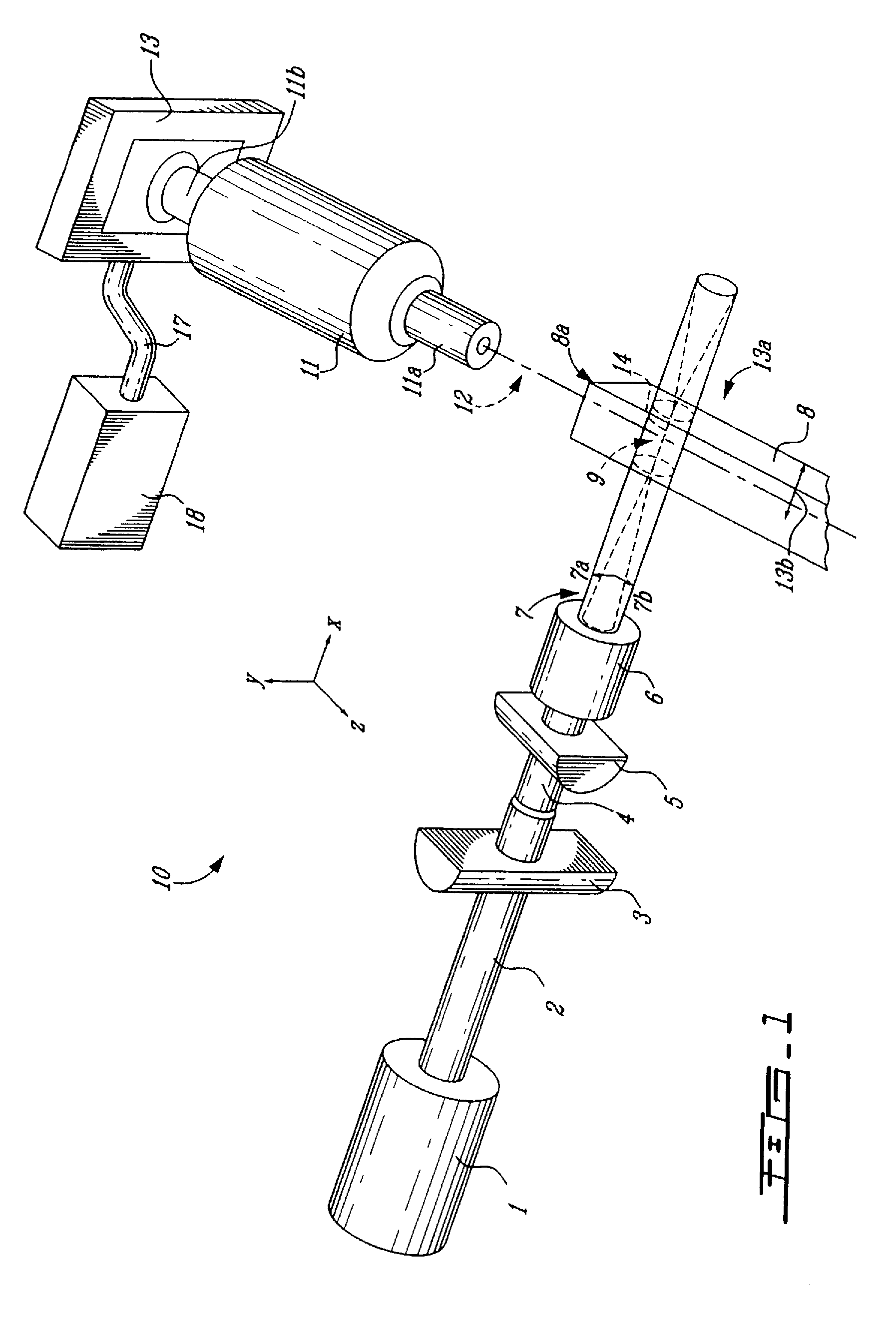
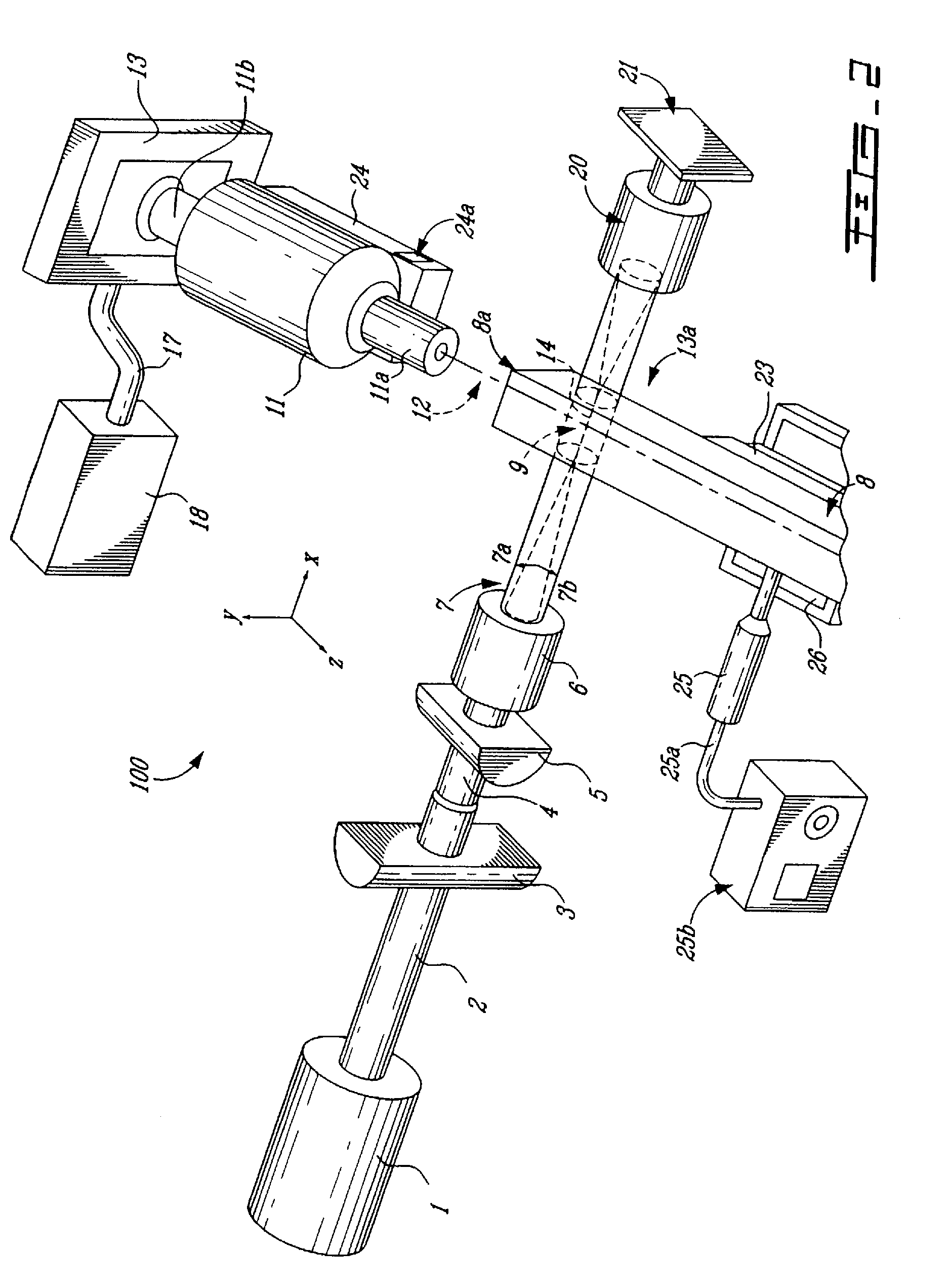
[0019]Generally stated, there is provided a method and an apparatus for illuminating a sample in a light profile microscope (LPM) to obtain an optimized spatial resolution in a recorded image, under broad field conditions.

[0020]As will be explained further hereinbelow, image properties depend on a geometry of a source beam in the sample, including the size, shape, and alignment distance of the source beam behind an IT surface of the sample. This source beam geometry is in turn dictated by characteristics of the optical imaging system (OIS) used to form the LPM image.

[0021]As described hereinabove, the OIS used by a LPM comprises a combination of lenses and / or mirrors so arranged as to form an image of the sample in the LPM.

[0022]The OIS defines an object plane, and an image plane in which it forms an image of a system object consisting of a field of refracted or emitted light located in the OIS object plane. Each of the object plane and the image plane is oriented along transverse d...


PUM

PropertyMeasurementUnit
angleaaaaaaaaaa
wavelengthsaaaaaaaaaa
light profile microscopeaaaaaaaaaa

Abstract

An apparatus and method allowing an optimized illumination in a light profile microscope by excitation of a sample with an elliptically collimated beam. The beam, which is typically supplied by a laser is collimated with unequal beam waist radii (and Rayleigh ranges) along major and minor axes orthogonal to a propagation direction, and approximates a plane sheet of illumination. The plane sheet of illumination is aligned with a thinnest width dimension thereof along the optic axis of the microscope objective, and with a center thereof at the object plane of the objective. Excitation light in a test sample is thereby confined to within a narrow thickness of the object plane of the objective lens, which minimizes out-of focus light in the image. The major axis width of the plane illumination sheet is typically a factor of ten or more greater than the minimum width, allowing a large area of the test sample to be illuminated and imaged. This excitation arrangement optically emulates the operation of micro-toming a thin cross section of a material for analysis, and provides optimum resolution and field in a light profile microscope.

Description

CROSS-REFERENCE TO RELATED APPLICATIONS[0001]This application is a National Entry Application of PCT application no PCT / CA2005 / 000467 filed on Mar. 30, 2005 and published in English under PCT Article 21(2), which itself claims priority on U.S. provisional application No. 60 / 557,385, filed on Mar. 30, 2004. All documents above are herein in their entirety by reference.FIELD OF THE INVENTION[0002]The present invention relates to light profile microscopy (LPM). More specifically, the present invention is concerned with an apparatus and a method for illuminating a test material in a light profile microscope, so as to provide an optimized image resolution under broad field conditions.BACKGROUND OF THE INVENTION[0003]Light profile microscopy is an imaging method for obtaining direct images of cross sections of thin films using a light profile microscope (LPM) (see for example U.S. Pat. No. 6,614,532). The cross sectional images thus obtained may be used to identify the number, dimensions,...

Claims


Application Information

Patent Timeline
Patent Type & Authority Patents(United States)
IPC IPC(8): G02B21/06G01N21/84G02B21/08
CPCG01N21/8422G02B21/088
Inventor POWER, JOAN F.
Owner POWER JOAN F
Why Eureka
Try Eureka