X-ray device that emits an x-ray beam with a scanning-like movement

a scanning-like movement and x-ray technology, applied in the field of x-ray devices, can solve problems such as inability to prevent, and achieve the effect of improving the quality of x-ray images

Inactive Publication Date: 2007-10-23
SIEMENS AG
View PDF11 Cites 33 Cited by
  • Summary
  • Abstract
  • Description
  • Claims
  • Application Information

AI Technical Summary

Benefits of technology

[0006]It is an object of the present invention to provide an x-ray device in which an improvement in the quality of x-ray images, in particular with regard to obtaining a sharp image over the entire region, can be achieved in a low-cost manner.
[0009]By tilting the x-ray tube in accordance with the invention with a mounting arrangement for the x-ray tube, the emitted x-ray beam is moved over the examination region so that the fan-shaped beam always is gated from the region of highest image resolution or image sharpness of the emitted x-ray beam (which is on the side of the x-ray beam facing the rotary anode), and thus overall a uniform and high image definition or high image resolution is ensured over the examination region in a simple manner.
[0010]The image sharpness can be still further improved in an embodiment wherein, in combination with the tilting of the x-ray tube, the slit-shaped diaphragm can be moved over the examination region substantially in the direction of the rotational axis of the rotary anode and substantially synchronously with the movement of the fan-shaped x-ray beam. This ensures that the region of highest image resolution of the x-ray beam is always gated by the slit-shaped diaphragm.
[0011]The use of the inventive x-ray device can be expanded in an advantageous manner by the opening of the slit-shaped diaphragm being adjusted to cover the entire examination region, i.e. in the whole-field range. The x-ray device is thereby made usable for all types of whole-field examinations. The whole-field examination can be still further improved by the inventive x-ray device in an embodiment wherein the slit-shaped diaphragm is adjusted to cover the entire examination region and the x-ray beam is adjusted so its region of highest image resolution stays within this slit solely by the tilting of the x-ray tube in a defined range of the examination region. The tilting of the x-ray tube, which leads to an effective reduction of the anode inclination angle of the rotary anode, also leads to a reduction of the image definition differences over the examination region for a whole-field examination, and thus achieves a sharper image overall. By the tilting of the x-ray tube, the region with the highest image definition can additionally be adjusted to match the subject to be examined, such that a complete utilization of this region is possible.
[0012]According to a further embodiment of the invention, the focal spot can be enlarged in the radial direction of the rotary anode. The x-ray power can thereby be increased without loss due to the higher focal spot area, since the tube is inventively tilted to adjust the image definition. The advantage of an increase of the x-ray power is a reduction of the scan time. The shortening of the examination time thereby achieved is desirable for a patient to be examined with the x-ray device since the patient must remain still during the x-ray exposure, which (primarily in mammography) can be painful for the patient.

Problems solved by technology

It cannot be prevented, however, that regions of the x-ray beam that produce a different image resolution are gated by means of the movement of the diaphragm, such that the generated image exhibits differing image definitions.

Method used


Image

  • X-ray device that emits an x-ray beam with a scanning-like movement
  • X-ray device that emits an x-ray beam with a scanning-like movement
  • X-ray device that emits an x-ray beam with a scanning-like movement

Examples


Embodiment Construction

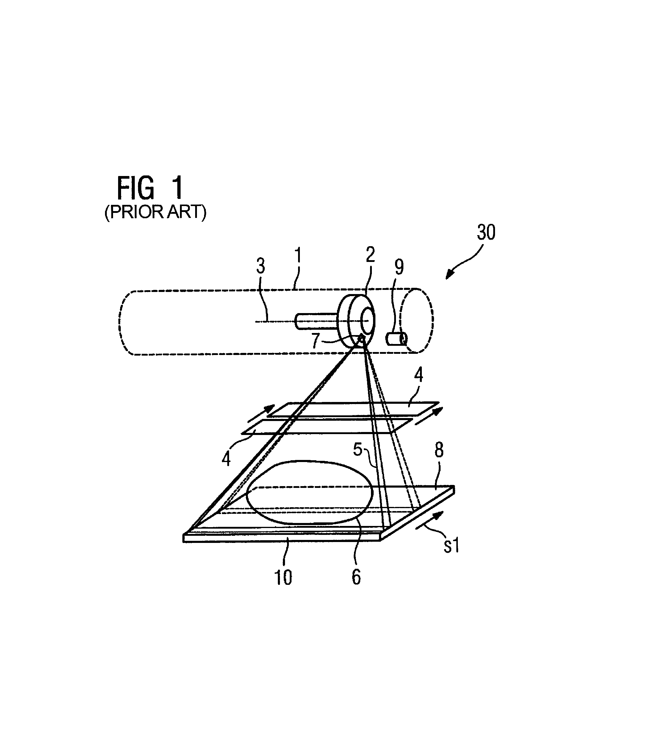
[0033]FIG. 1 shows a generally known x-ray device 30 for imaging a subject 6. The device 30 has a slit-shaped diaphragm 4 for generation of a fan-shaped x-ray beam 5 that can be gated from the overall emitted x-ray beam and moved over an examination region 8 in the manner of a scan. The x-ray device 30 has an x-ray tube 1 with a rotary anode 2 that can be rotated around a rotational axis 3, as well as a 2D detector 10 for acquiring the entire examination region of the subject 6. The lengthwise extent of the fan-shaped x-ray beam 5 is essentially parallel to the rotational axis 3 of the rotary anode 2; the scan direction over the examination region is essentially perpendicular to the plane of the fan shaped x-ray beam 5. The scanning ensues by movement of the opening of the slit-shaped diaphragm 4 in the arrow direction s1.

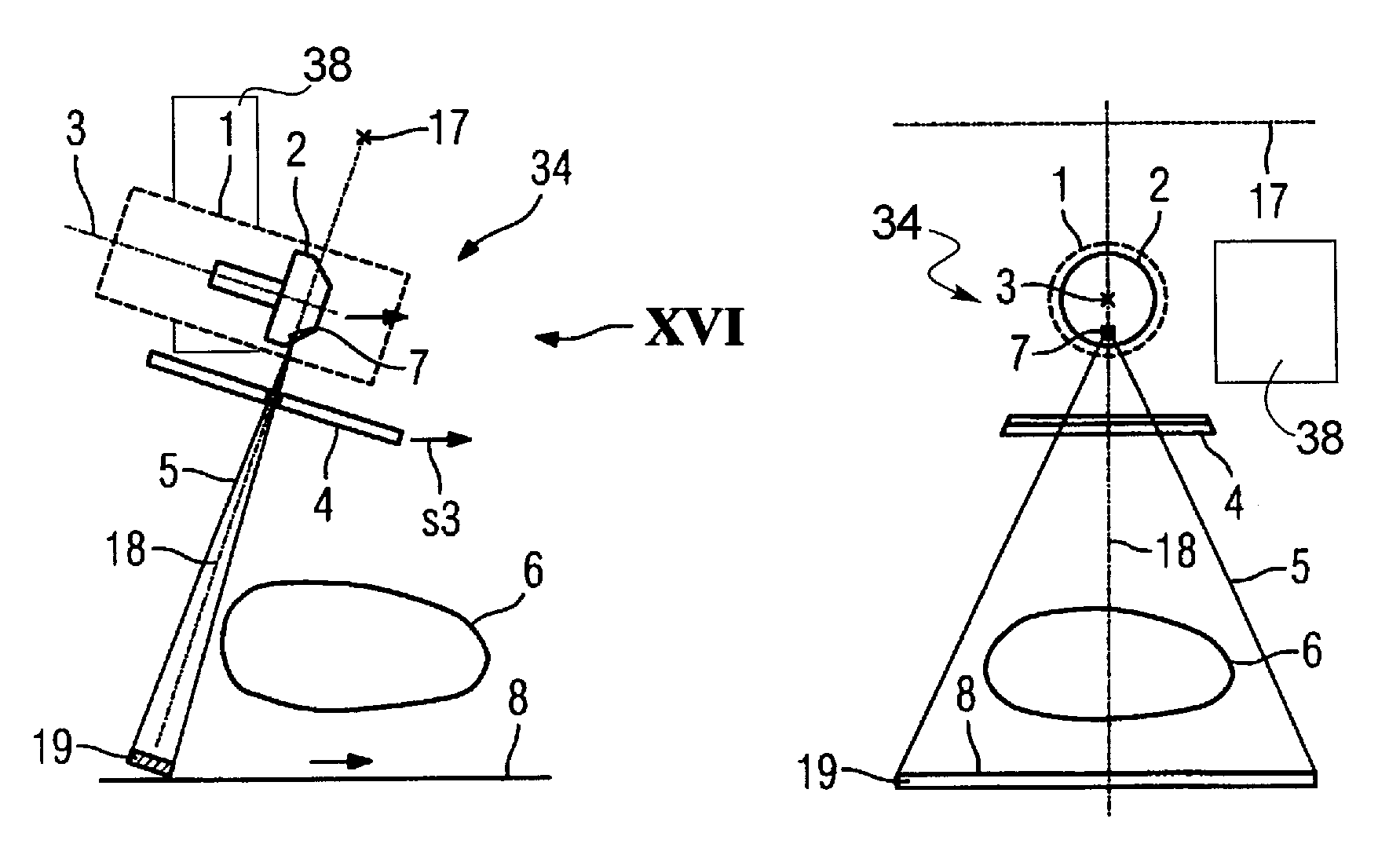
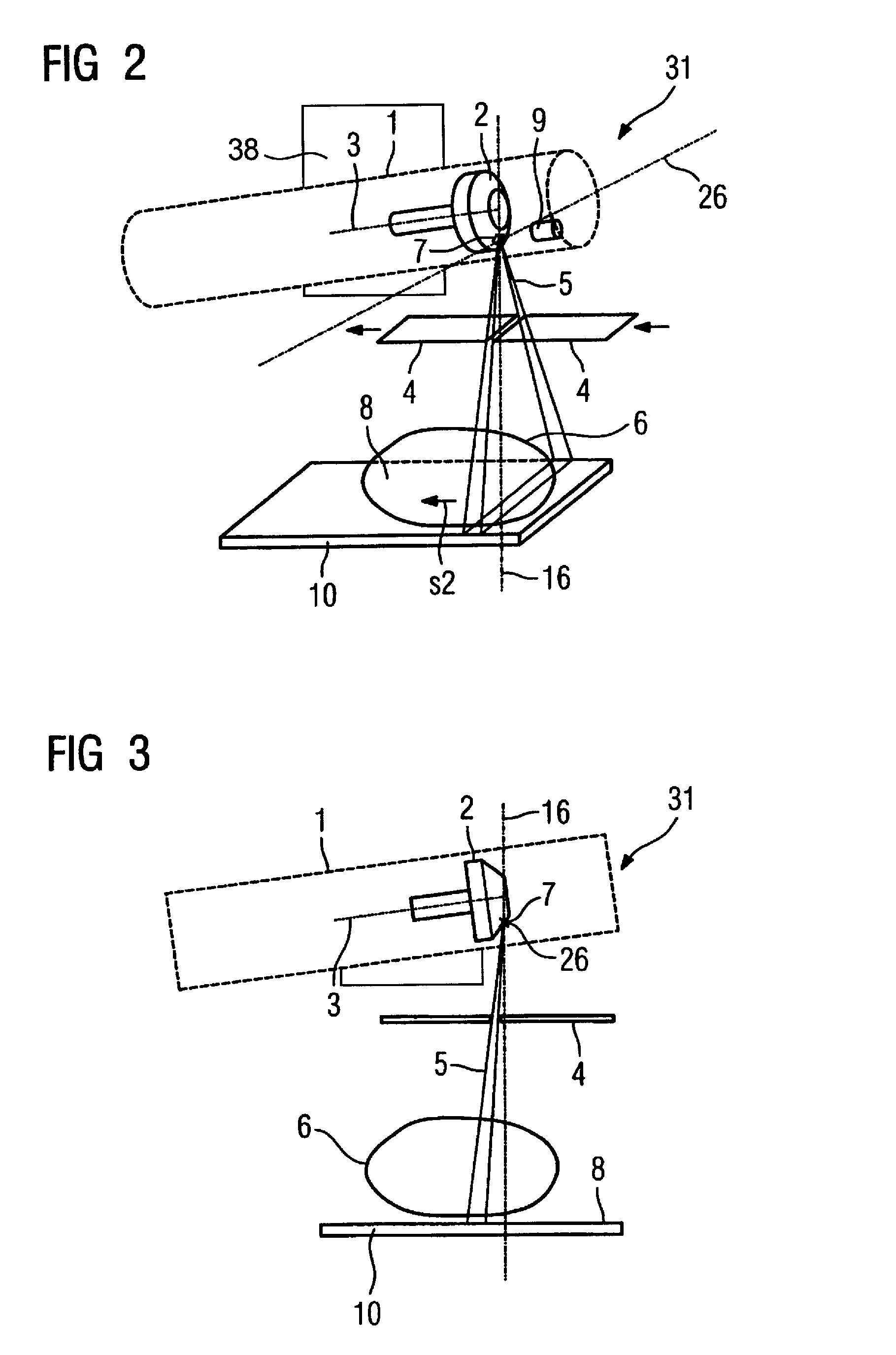
[0034]FIG. 2 through FIG. 7 respectively show an inventive x-ray device 31 for scanning a subject 6 on an examination region 8 in various tilt positions of the x-r...


PUM


Abstract

An x-ray device includes an x-ray tube for generation of an x-ray emanating from a focal spot of a rotary anode rotatable around a rotation axis and a slit-shaped diaphragm for generation of a fan-shaped x-ray beam that is gated from the x-ray and emission is moved through an examination region in the manner of a scan. To improve the image resolution, the fan-shaped x-ray beam can be moved over the examination region essentially in the direction of the rotational axis of the rotary anode by tilting the x-ray tube on the focal spot, with the x-ray tube being tilted on the focal spot so that the fan-shaped x-ray beam is always gated from the region of the overall emitted x-ray beam having the highest image resolution or the highest image definition in the movement through the examination region.

Description

BACKGROUND OF THE INVENTION[0001]1. Field of the Invention[0002]The present invention concerns an x-ray device, in particular for a mammography x-ray apparatus of the type that emits an x-ray beam that exhibits a movement in the manner of a scan of a subject.[0003]2. Description of the Prior Art[0004]In x-ray imaging, the imaging properties are negatively influenced (such as blurring) by the scatter radiation of the x-ray beam generated by an anode, for example a rotary anode. To prevent such scatter radiation, in addition to scattered-ray grids scan methods are used in which a fan-shaped x-ray beam is excised from the totality of emitted, x-rays by a slit-shaped diaphragm, and the diaphragm and the x-ray beam are moved in a grid-like manner over the subject to be imaged. Furthermore, to prevent scatter radiation it is known to provide a further slit diaphragm between the subject and the radiation detector that converts the x-ray radiation into an image signal. It is also known to d...

Claims


Application Information

Patent Timeline
Patent Type & Authority Patents(United States)
IPC IPC(8): G21K5/10
CPCA61B6/4021G21K1/04A61B6/502
Inventor FREUDENBERGER, JORGSCHARDT, PETER
Owner SIEMENS AG
Why Eureka
Try Eureka