Optical print head using a glass arm waveguide

a technology of optical print head and waveguide, which is applied in the field of optical mechanism, can solve the problems of high cost of optical disc drives, and the costly component of optical disc drives is the optical pickup unit (opu), and achieve the effects of reducing the number of disparate optical elements, reducing the number of alignments, and low numerical apertur

Inactive Publication Date: 2007-09-06
HEWLETT PACKARD DEV CO LP
View PDF13 Cites 2 Cited by
  • Summary
  • Abstract
  • Description
  • Claims
  • Application Information

AI Technical Summary

Benefits of technology

[0011] In another further preferred embodiment, a unitary, transparent glass / quartz (or any high transmit material and low birefringence for labeling wavelength) waveguide that utilizes optical elements that are placed onto the waveguide such that the waveguide creates a more compact assembly, employs a relatively low numerical aperture that can be used in the OPH for disk labeling, reduces the number of disparate optical elements, and reduces the number of alignments is disclosed.
[0012] The preferred optical mechanism, according to various embodiments of the present invention, offers the following advantages: lightness in weight; a more compact assembly; a relatively low numerical aperture; and decreased optical element / optical beam generating mechanism alignment complexity. In fact, in many of the preferred embodiments, these factors of shorter optical beam path length, lower numerical aperture, and decreased optical element / optical beam generating mechanism alignment complexity are optimized to an extent that is considerably higher than heretofore achieved in prior, known optical mechanisms.

Problems solved by technology

A costly component of an optical disc drive is the optical pickup unit (OPU).
The OPU is the optical mechanism by which an optical beam is generated, and then guided to the surface of an optical disc using a number of precisely arranged lenses and other components, including an objective lens, which have to be manufactured to high tolerances, and thus at high cost.
Therefore, optical disc drives typically only have one OPU for cost and complexity reasons.
Also, the alignments can be costly as well as time consuming.
Finally, these type of wave guides utilize an extremely long path length.

Method used


Image

  • Optical print head using a glass arm waveguide
  • Optical print head using a glass arm waveguide
  • Optical print head using a glass arm waveguide

Examples


Embodiment Construction

[0025] In the following detailed description of exemplary embodiments of the invention, reference is made to the accompanying drawings that form a part hereof, and in which is shown by way of illustration specific exemplary embodiments in which the invention may be practiced. These embodiments are described in sufficient detail to enable those skilled in the art to practice the invention. Other embodiments may be utilized, and logical, mechanical, and other changes may be made without departing from the spirit or scope of the present invention. The following detailed description is, therefore, not to be taken in a limiting sense, and the scope of the present invention is defined only by-the appended claims.

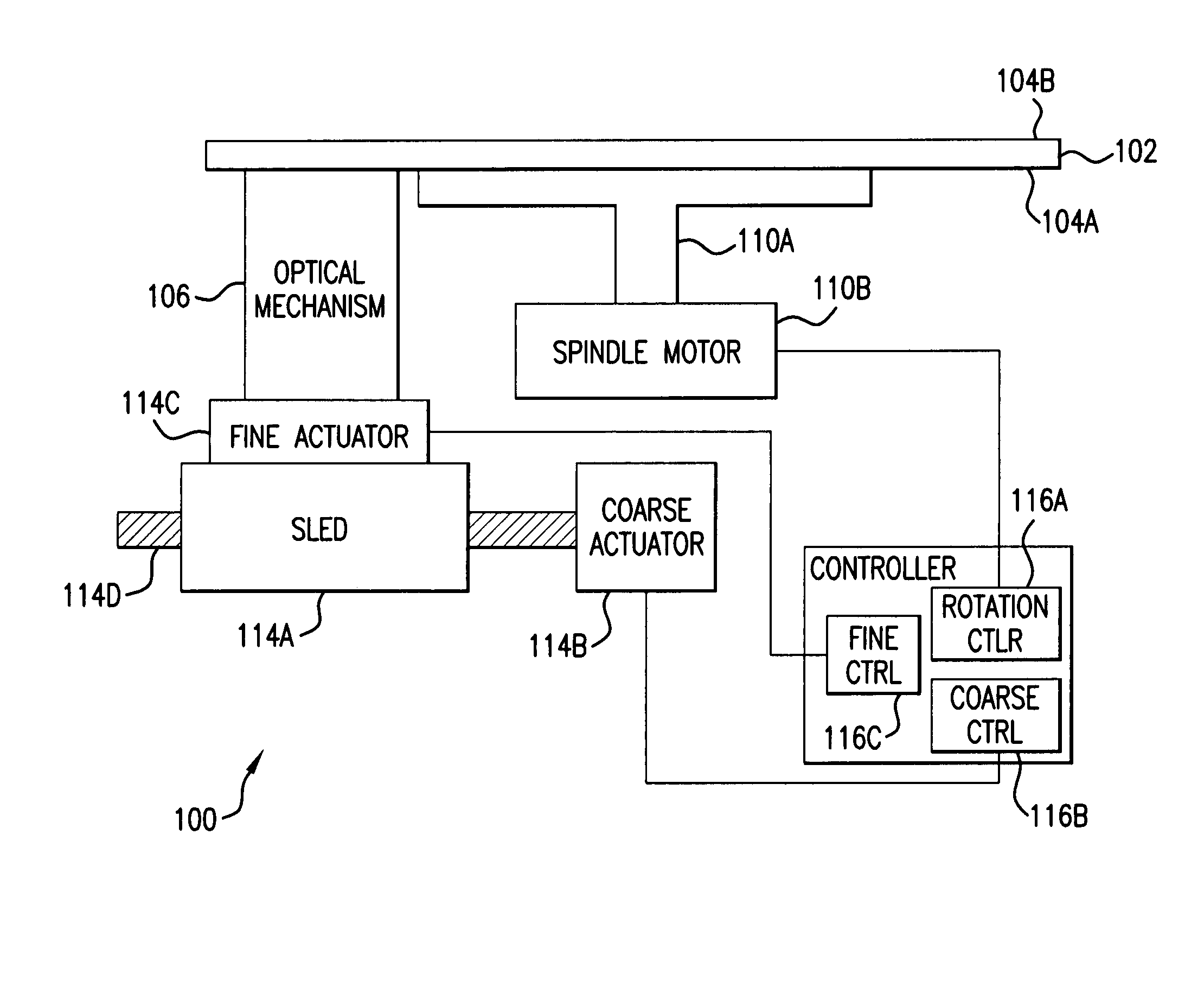
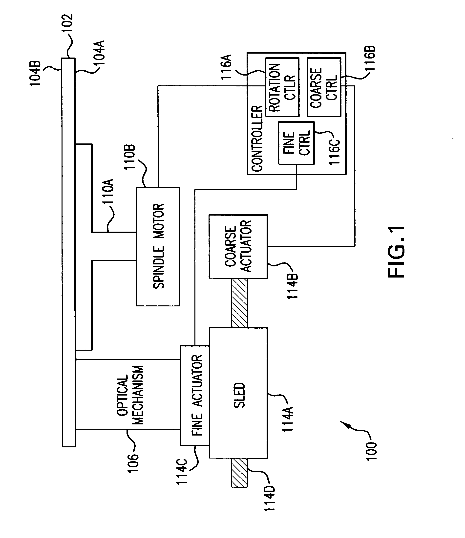
[0026] With reference first to FIG. 1, there is illustrated one preferred embodiment for use of the concepts of this invention. FIG. 1 shows an optical disc drive 100, according to an embodiment of the invention. The optical drive 100 is for reading from and / or writing to an opti...


PUM

PropertyMeasurementUnit
total thicknessaaaaaaaaaa
widthaaaaaaaaaa

Abstract

This invention relates to an optical mechanism comprising: an optical beam generating mechanism to generate an optical beam; and a unitary, transparent waveguide for guiding the optical beam to an optically writable surface wherein optical elements for guiding the optical beam are coated onto the waveguide to create a relatively compact optical system, a relatively low exit numerical aperture for the exit pupil, and for bending and re-directing the optical beam.

Description

BACKGROUND OF THE INVENTION [0001] 1. Field of the Invention [0002] This invention relates to an optical mechanism comprising: an optical beam generating mechanism to generate an optical beam; and a unitary, transparent waveguide for guiding the optical beam to an optically writable surface wherein optical elements for guiding the optical beam are coated onto the waveguide to create a relatively compact optical system, a relatively low exit numerical aperture for the exit pupil, and for bending and re-directing the optical beam. [0003] 2. Description of the Related Art [0004] Prior to the present invention, as set forth in general terms above and more specifically below, it is known that optical disc drives have historically been used to optically read data from and optically write data to data regions of optical discs. More recently, optical disc drives have been used to optically write images to label regions of optical discs. For example, a type of optical disc is known in which ...

Claims


Application Information

Patent Timeline
Patent Type & Authority Applications(United States)
IPC IPC(8): B41J15/14G11B7/12G11B7/135
CPCB41J3/4071G02B6/10G11B7/0037G11B23/40G11B7/1372G11B7/24094G11B7/124
Inventor VAN BROCKLIN, ANDREW L.WU, KUOHUA
Owner HEWLETT PACKARD DEV CO LP
Why Eureka
Try Eureka