Multiple-use projection system

a projection system and multi-use technology, applied in the field of projection exposure method, can solve the problems of reducing the maximum achievable resolution, increasing the image field size at the expense of increasing the resolution, and achieving the effect of high substrate throughput and higher resolution

Inactive Publication Date: 2008-06-26
CARL ZEISS SMT GMBH
View PDF8 Cites 11 Cited by
  • Summary
  • Abstract
  • Description
  • Claims
  • Application Information

AI Technical Summary

Benefits of technology

[0027]This specific type of optimization can be implemented with conventional software for optical design (for example software with the trademark “CODE V®”), in order to provide projection objectives that can be produced with an acceptable technical outlay and which are optimized only for specific combinations of exposure parameters, it being possible for other parameter combinations that are ...

Problems solved by technology

Outside the image field, whose image field size (shape and dimensions) is pre-scribed to the optics designer before the development of a new design, the correction state generally worsens drastically such that no exposure radiation that can be used in practice for imaging exists outside the image field.
Since it becomes ever more difficult with increasing numerical aperture to correct the image quality for large image fields, very high aperture projection objectives generally have smaller image fields than objectives with a lower numerical aperture.
As a rule, however, the rise in imag...

Method used


Image

  • Multiple-use projection system
  • Multiple-use projection system
  • Multiple-use projection system

Examples


Embodiment Construction

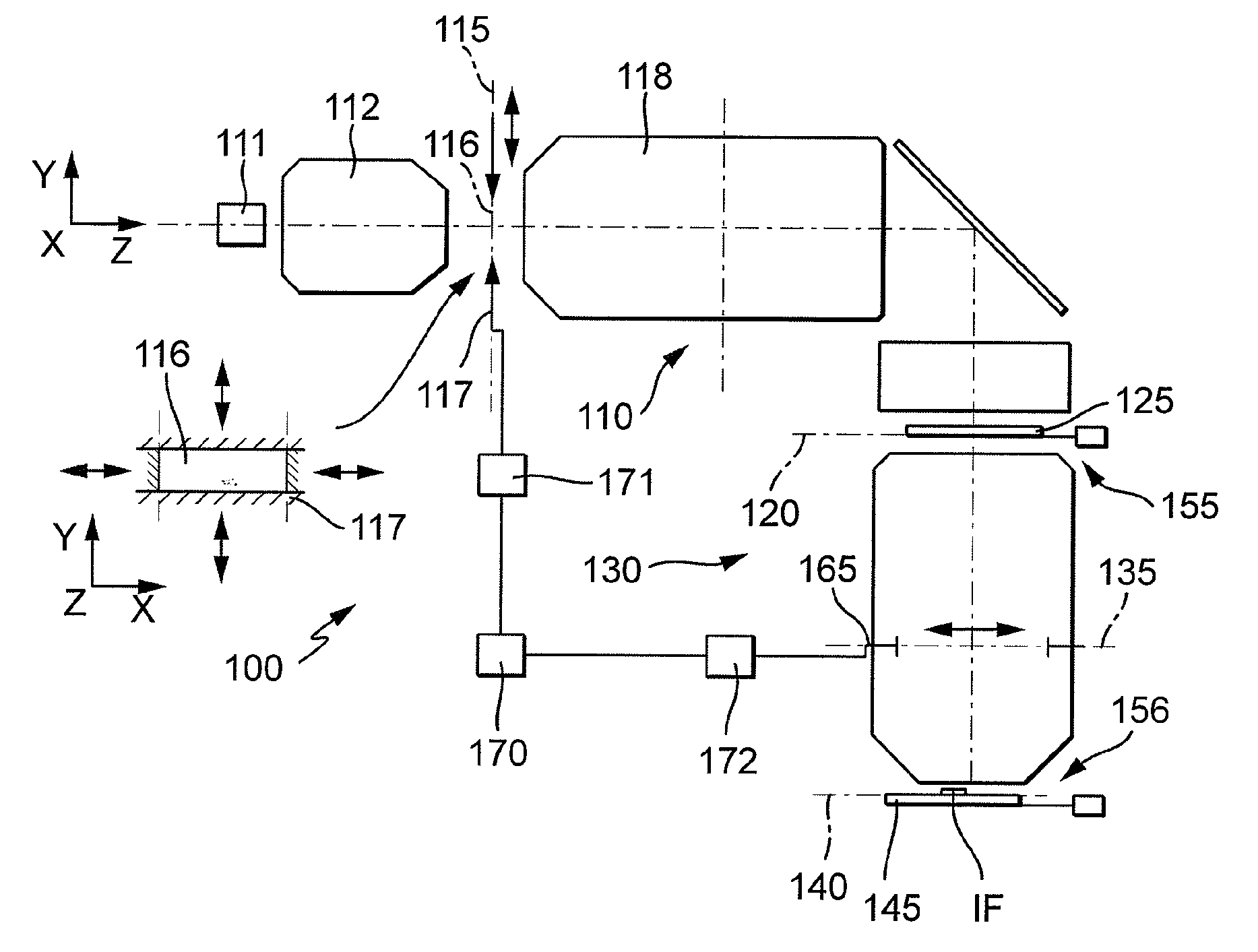
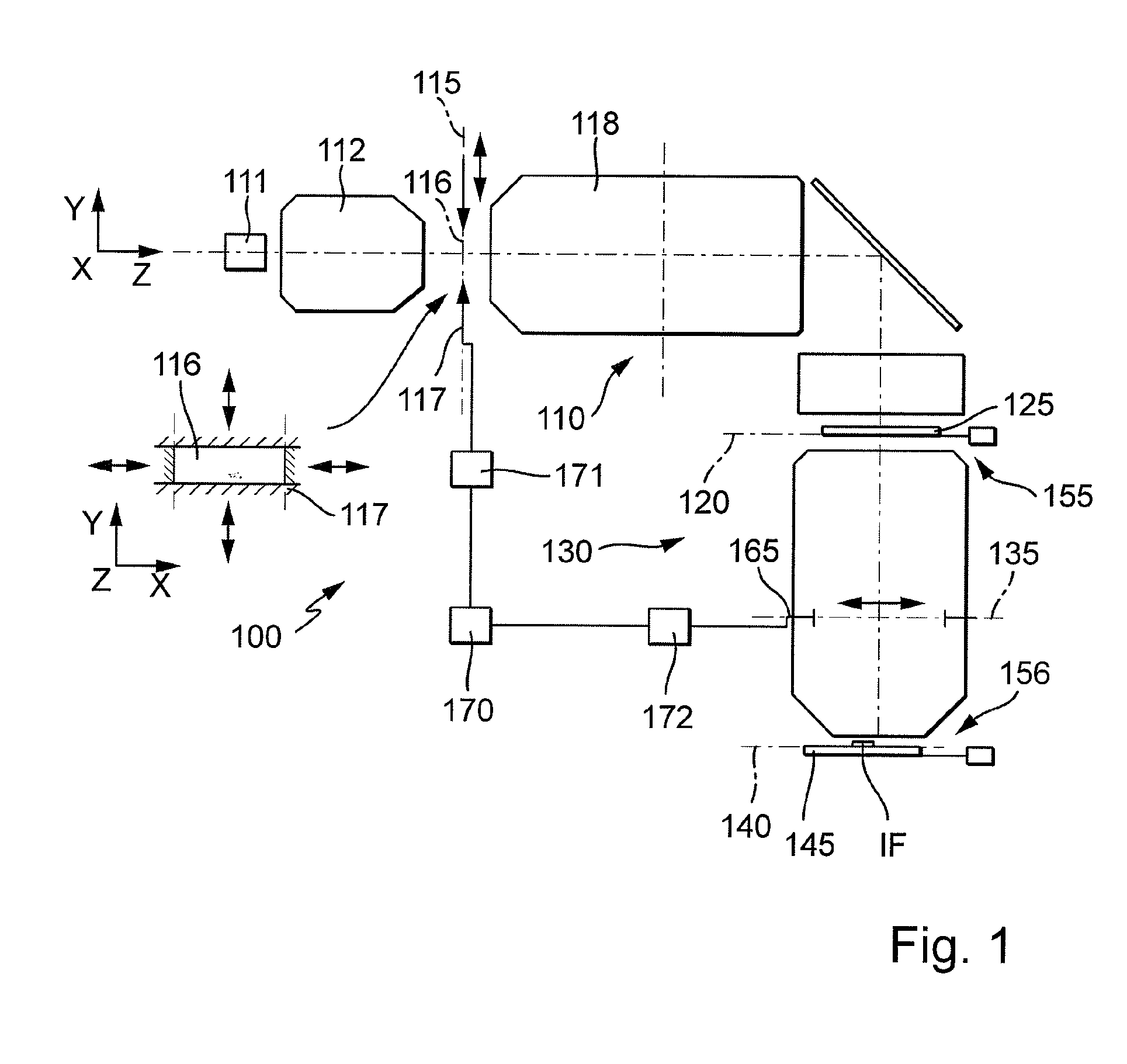
[0035]FIG. 1 shows an embodiment of a projection exposure machine 100 for the microlithographic production of integrated circuits and other finely structured components in the case of resolutions as far as fractions of 1 μm. The projection exposure machine comprises an illumination system 110 for illuminating a photomask (reticle) 125 arranged in the exit or image plane 120 of the illumination system, and also a projection objective 130 that images the pattern, arranged in its object plane 120, of the photomask 125 into the image plane 140 of the projection objective on a reducing scale. By way of example, the surface of a semiconductor wafer 145 coated with a photosensitive layer is located in the image plane 140. An excimer laser with an operating wavelength of 248 nm that can be used in the deep ultraviolet (DUV) region serves as light source 111 of the illumination system 110, it also being possible, for example, to use laser with a wavelength of 193 nm or 157 nm in the case of ...


PUM


Abstract

Projection exposure methods and systems for exposing substrates are disclosed. The methods and systems feature projection objectives capable of multiple exposure configurations having different image side numerical apertures and different image field sizes.

Description

CROSS-REFERENCE TO RELATED APPLICATIONS[0001]This application is a continuation application of and claims priority to International Patent Application No. PCT / EP2006 / 005168, filed on May 31, 2006, which claims benefit of Provisional Patent Application No. 60 / 689,259, filed on Jun. 10, 2005. The entire contents of both International Patent Application No. PCT / EP2006 / 005168 and Provisional Patent Application No. 60 / 689,259 are incorporated herein by reference.BACKGROUND[0002]1. Field of the Disclosure[0003]The disclosure relates to a projection exposure method for exposing substrates, arranged in the region of an image plane of a projection objective, with at least one image of a pattern, arranged in the region of an object plane of the projection objective, of a mask and to a projection objective that can be used in the case of such a projection exposure method, and to a method for producing a projection objective that can be used in the case of such a projection exposure method.[000...

Claims


Application Information

Patent Timeline
IPC IPC(8): G03B27/72
CPCG03F7/70066G03F7/70341G03F7/7025G03F7/20G02B15/00G03B21/14
Inventor KAISER, WINFRIEDULRICH, WILHELMFELDMANN, HEIKODODOC, AURELIAN
Owner CARL ZEISS SMT GMBH
Why Eureka
Try Eureka