Automatic focusing apparatus
- Summary
- Abstract
- Description
- Claims
- Application Information
AI Technical Summary
Benefits of technology
Problems solved by technology
Method used
Image
Examples
first embodiment
(First Embodiment)
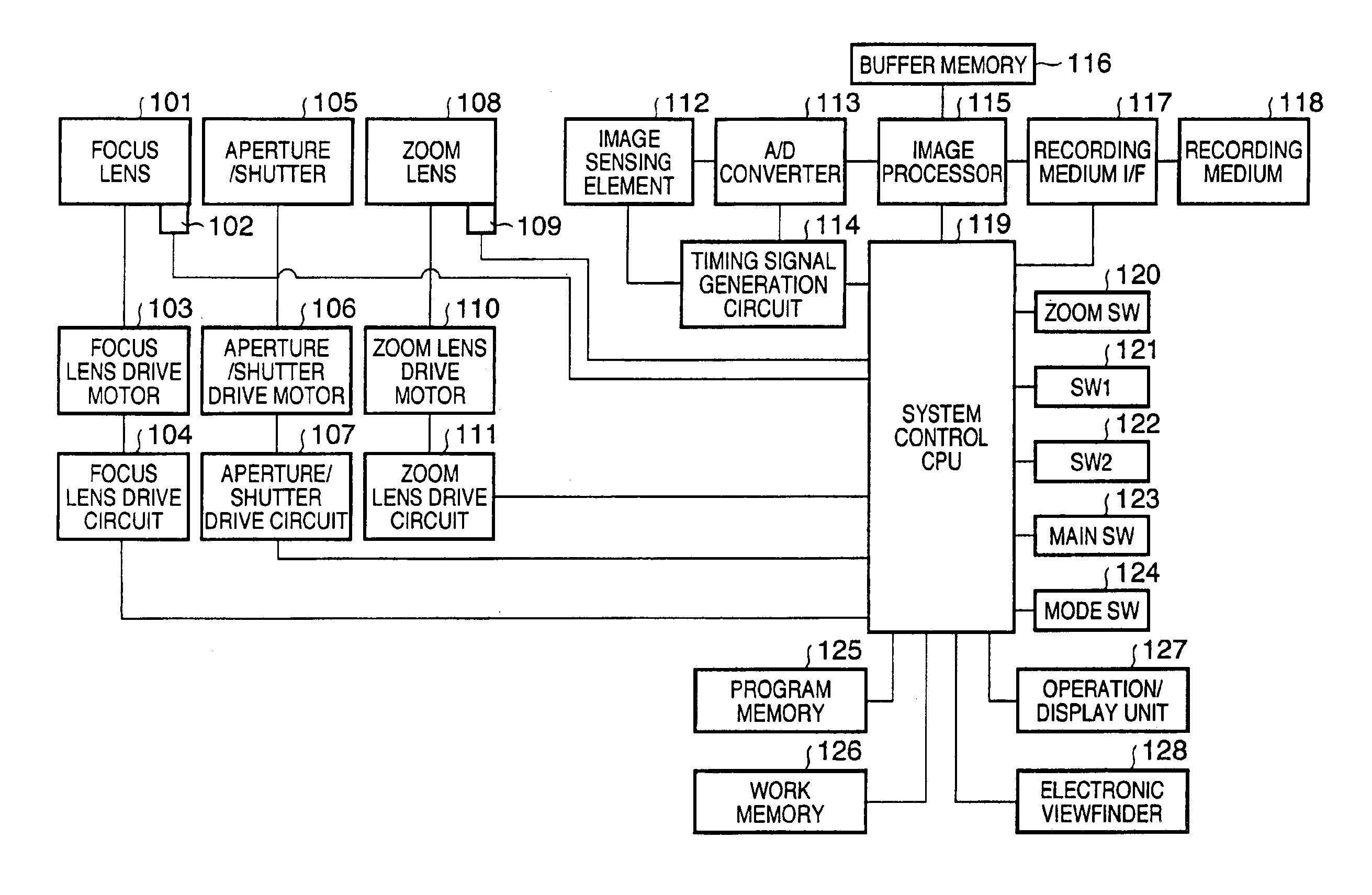
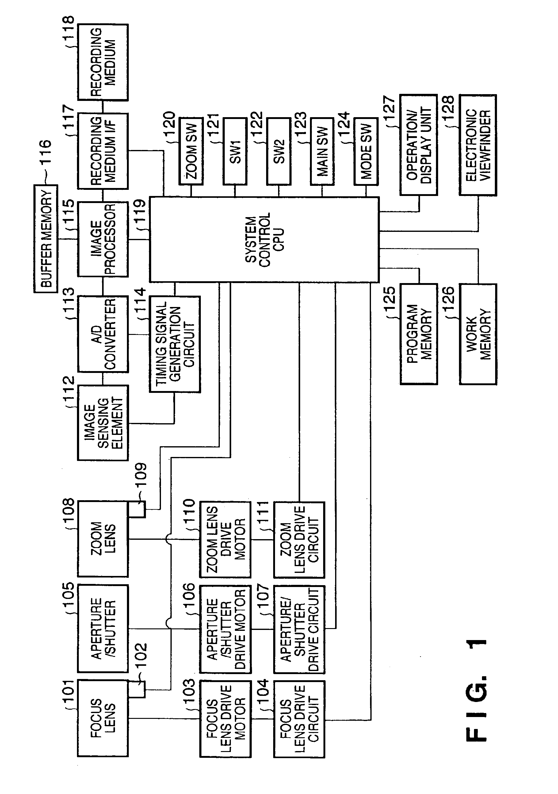
[0030]FIG. 1 is a block diagram of a digital camera as an image recording apparatus to which an automatic focusing apparatus according to the present invention is applied. Reference numeral 101 denotes a focus lens used to adjust a focus on an image sensing element 112 (to be described later); 102, a photointerrupter for detecting the initial position of the focus lens 101; 103, a motor for driving the focus lens 101; and 104, a focus lens drive circuit for supplying a drive signal to the motor 103 to drive the focus lens 101.
[0031]Reference numeral 105 denotes light control members including an aperture, shutter, and the like; 106, a motor for driving the aperture / shutter 105; and 107, an aperture / shutter drive circuit for supplying a drive signal to the motor 106 to drive the aperture / shutter 105.
[0032]Reference numeral 108 denotes a zoom lens for changing the focal length of a photographing lens; 109, a photointerrupter for detecting the initial position of the ...
second embodiment
(Second Embodiment)
[0074]In the above description, the state of SW2 is checked upon starting the AF operation, and the scan count is then set. Alternatively, the state of SW2 may be checked during the AF operation. The operation of such embodiment will be explained below.
[0075]FIGS. 7 and 8 are flow charts for explaining the main exposure AF operation in step S302 in FIG. 3. In step S601, a scan execution count is reset to zero. Note that the scan execution count indicates the order of the current scan in a plurality of scans as well as that set in step S401 in FIGS. 4 and 5 in the first embodiment.
[0076]In step S602, the state of SW2 is checked. If SW2 is ON, the flow advances to step S603; otherwise, the flow advances to step S605.
[0077]In step S603, a total scan count is set to be 1. Note that the total scan count indicates the number of scans executed per AF operation as well as that set in step S403 in FIGS. 4 and 5 in the first embodiment. In step S604, a scan interval is set ...
third embodiment
(Third Embodiment)
[0096]In the above description, the state of SW2 is checked upon completion of the first scan. If SW2 is ON, the second scan is skipped. Alternatively, the state of SW2 may be checked during the first scan. The operation of such embodiment will be described below.
[0097]FIGS. 9 and 10 are flow charts for explaining the main exposure AF operation in step S302 in FIG. 3. In step S701, a scan execution count is reset to zero. Note that the scan execution count indicates the order of the current scan in a plurality of scans as well as that set in step S401 in FIGS. 4 and 5 in the first embodiment.
[0098]In step S702, the state of SW2 is checked. If SW2 is ON, the flow advances to step S703; otherwise, the flow advances to step S705.
[0099]In step S703, a total scan count is set to be 1. Note that the total scan count indicates the number of scans executed per AF operation as well as that set in step S403 in FIGS. 4 and 5 in the first embodiment. In step S704, a scan inter...
PUM
 Abstract
Description
Claims
Application Information
 - R&D
- Intellectual Property
- Life Sciences
- Materials
- Tech Scout
- Unparalleled Data Quality
- Higher Quality Content
- 60% Fewer Hallucinations
Browse by: Latest US Patents, China's latest patents, Technical Efficacy Thesaurus, Application Domain, Technology Topic, Popular Technical Reports.
© 2025 PatSnap. All rights reserved.Legal|Privacy policy|Modern Slavery Act Transparency Statement|Sitemap|About US| Contact US: help@patsnap.com


