
Electrically Powered Infrared Based Thermal Weed Control System

Active Publication Date: 2017-08-03
STW LLC
View PDF2 Cites 5 Cited by
  • Summary
  • Abstract
  • Description
  • Claims
  • Application Information

AI Technical Summary

Benefits of technology

The present invention is a new and improved electrically powered infrared based thermal weed control system. It has advantages of prior art weed control systems without their disadvantages. It is easy and efficient to manufacture and market. It is durable and reliable. It is susceptible of a low cost of manufacture and sale. The electrically generated infrared is precise, focused, and controllable, and it does not need to rely on shields or barriers to isolate the desirable plants from the undesirable plants. It is suitable for thermal weed control in whole categories of agricultural crops where combustion generated infrared is impractical or impossible. The electrically generated infrared emitters describe a virtual straight path of treatment that allows for precise targeting of weeds.

Problems solved by technology

While these devices fulfill their respective, particular objectives and requirements, they do not describe electrically powered infrared based thermal weed control system that allows heating weeds to an appropriate temperature and for an appropriate time sufficient to control weeds in a safe, ecological, convenient, and economical manner.
Although open flame combustion based systems exist, these are very dangerous and hard to control and will not effectively control weeds in a large number of crop fields as such systems would ultimately damage or kill the desired crops.

Method used


Image

  • Electrically Powered Infrared Based Thermal Weed Control System
  • Electrically Powered Infrared Based Thermal Weed Control System
  • Electrically Powered Infrared Based Thermal Weed Control System

Examples


experiment 1

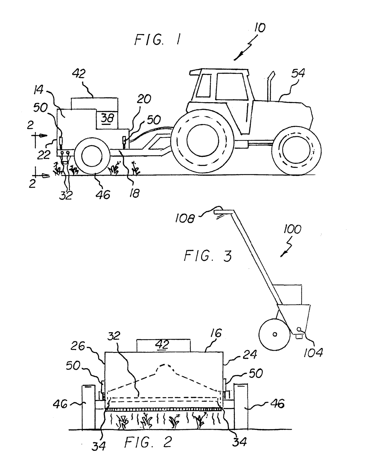
[0033]Propane test. In this test, a propane powered thermal weed control system was pulled by a vehicle. The system involved a propane tank coupled to hoses that fed flame torches. On either side of each flame source, there were metal plates whose intention was to isolate the flame's impact. The power of the flame was controllable via a valve system. The propane was turned on and the flame was lit manually. Controlling the valve system proved very difficult since each time the valve was turned down too far, the propane needed to be re-lit, otherwise there would be a source leaking propane into the air, which could spontaneously combust once in contact with the other flame sources.

[0034]The apparatus was pulled across an open field (and later crops), and it immediately became apparent that the combustion based system was both very difficult to control and extremely dangerous. For safety, a second vehicle had to follow, at a distance, with a fire extinguisher. The heat generated by th...

experiment 2

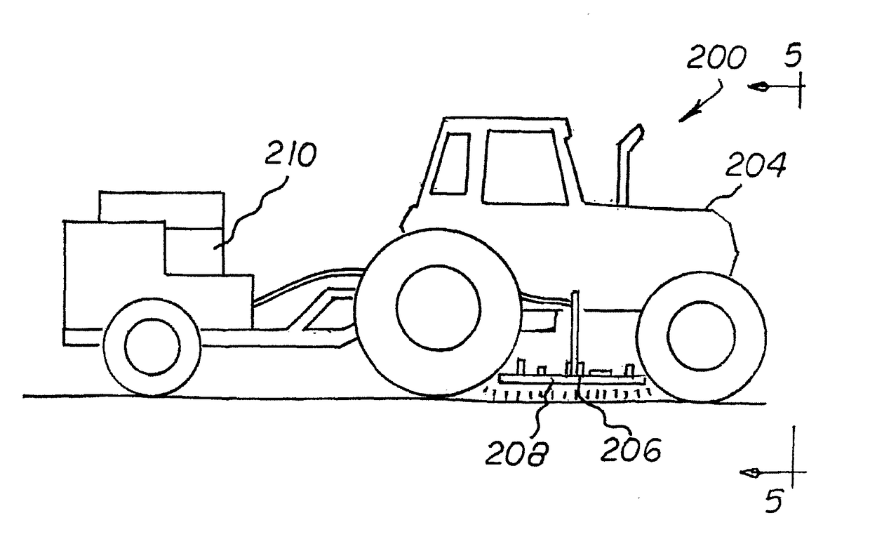
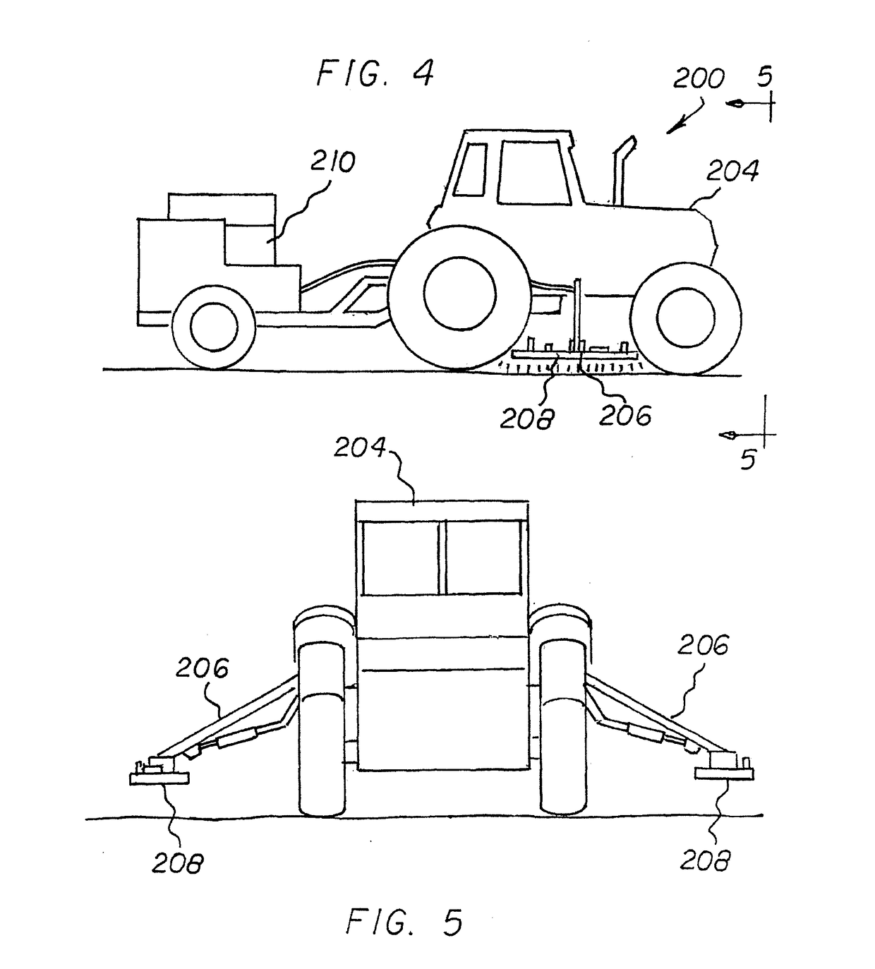
[0037]Electrical Infrared test. In view of the foregoing disadvantages discovered as to typical combustion based heaters, a test was conducted using a prototype electrically powered infrared weed control system. The electrical infrared emitter performed much like a flashlight in terms of targeting, with the emitter producing invisible infrared radiation, much in the way that a flashlight provides visible light. Particularly, the infrared emitter was located in a downward facing chamber and connected to an electrical power source via electrical switches and controls. In this experiment, the power source was a conventional generator that can be found in most home improvement stores. The generator was pulled behind a tractor and the housing was mounted on a movable arm off of the tractor, which allowed for adjustment of vertical position. An electrical controller allowed for electric power to the emitter to be adjusted. There was no flame or combustion or fuel whatsoever (other than th...


PUM


Abstract

An electrically powered infrared based thermal weed control system. A housing has a downwardly facing chamber. At least one electrically powered infrared heating element is mounted within the chamber. A source of electrical power is electrically coupled to the electrically powered infrared heating element. A control assembly varies the electrical power to the electrically powered infrared heating elements and the heat generated for controlling undesired vegetation there adjacent using targeted infrared radiation emitted by the electrically powered infrared heating element.

Description

FIELD OF THE INVENTION[0001]The present invention relates to an electrically powered infrared based thermal weed control system and more particularly pertains to heating weeds to an appropriate temperature and for an appropriate time sufficient to control weeds in a safe, ecological, convenient, and economical manner.BACKGROUND OF THE INVENTION[0002]The use of weed control systems of known designs and configurations is known in the prior art. More specifically, weed control systems of known designs and configurations previously devised and utilized for the purpose of controlling weeds are known to consist basically of familiar, expected, and obvious structural configurations, notwithstanding the myriad of designs encompassed by the crowded prior art which has been developed for the fulfillment of countless objectives and requirements.[0003]While these devices fulfill their respective, particular objectives and requirements, they do not describe electrically powered infrared based th...

Claims


Application Information

Patent Timeline
IPC IPC(8): A01M21/04H05B3/00
CPCH05B3/0033A01M21/04
Inventor KENT, HUGH C.REISCHMANN, MICHAEL
Owner STW LLC
Learn More