Rotating bed with improved stability

a technology of rotating beds and stability, applied in the field of rotating beds, can solve the problems of not being able to project in the lateral direction beyond the structure of the bed frame in the lateral direction, unable to reach the stability limit, and unable to completely tip, so as to achieve the effect of improving stability

Inactive Publication Date: 2006-08-08
BARTHELT HANS PETER
View PDF9 Cites 44 Cited by
  • Summary
  • Abstract
  • Description
  • Claims
  • Application Information

AI Technical Summary

Benefits of technology

[0010]It is an object of the invention to provide a rotatable bed that has improved stability when in a rotated position which prevents tipping over.
[0013]The utilization of at least one additional support leg is particularly advantageous in connection with steerable wheels. Depending on the caster of the steerable wheels, the width of the floor coverage area may vary by up to 10 cm according to the steering position of the wheels. Relative to a normal floor coverage area width of approximately 75 cm, this is a considerable value that can significantly influence the stability.
[0014]The utilization of wheels or legs makes it possible to raise the lower edge of the base off the floor such that hospital personnel caring for the patient lying in the bed can stand as close to the bed as possible, because the front of their feet can be placed underneath the raised base. If the bed is equipped with wheels, two wheels need to be provided with brakes so as to ensure that the bed cannot roll away when in the chair position. The brakes should be arranged on the wheels that are situated distant from the foot section when in the chair position.
[0015]Depending on the design of the bed, one or more support legs may be utilized rigidly or movably. Rigid support legs are particularly used when the bed is essentially arranged in a stationary fashion. Movable support legs equipped with the above-mentioned wheels preferably are utilized on mobile beds, such as beds used, for example, in nursing homes and the like. The utilization of a movable support leg makes it possible to eliminate a stumbling hazard as would be created if the support leg is significantly elevated relative to the floor and laterally projects beyond the structure of the bed in the sleeping position.
[0019]The articulation arrangement makes it possible to move the support leg along a path with at least one component that is aligned transverse to the longitudinal direction of the bed in the sleeping position. Such a travel path also is effected if the support leg needs to be turned about an axis at least approximately vertical in order to be moved from the idle or parking position into the supporting position.

Problems solved by technology

However, it cannot project beyond the structure of the bed frame in the lateral direction.
This arrangement may approach its stability limit, particularly when the bed frame is raised, depending on the weight of the user, the distance by which the user leans forward over the seat edge in the chair position, the weight of the base, the size of the floor coverage area of the base and any impermissible manipulations the patient during the rotation.
If the stability limit is exceeded, the bed could completely tip over on the side concerned, and the user can be trapped underneath the bed.

Method used


Image

  • Rotating bed with improved stability
  • Rotating bed with improved stability
  • Rotating bed with improved stability

Examples


Embodiment Construction

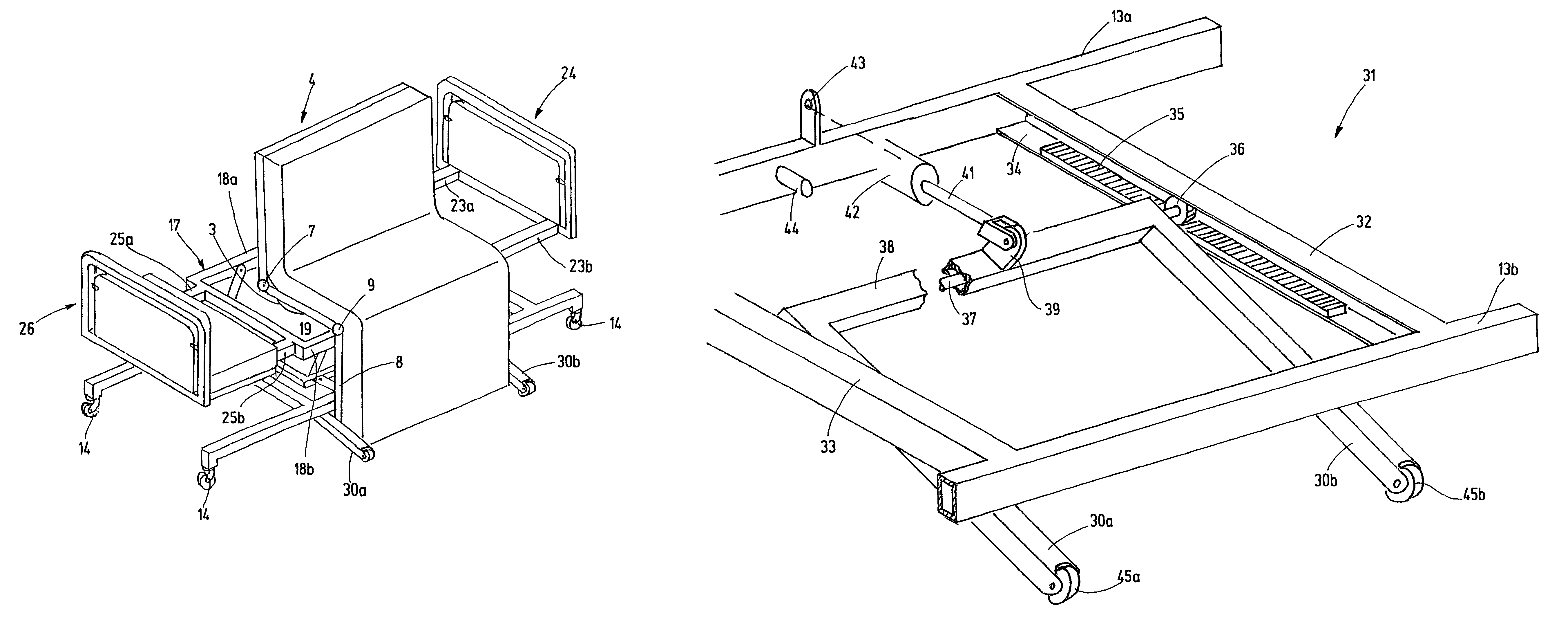
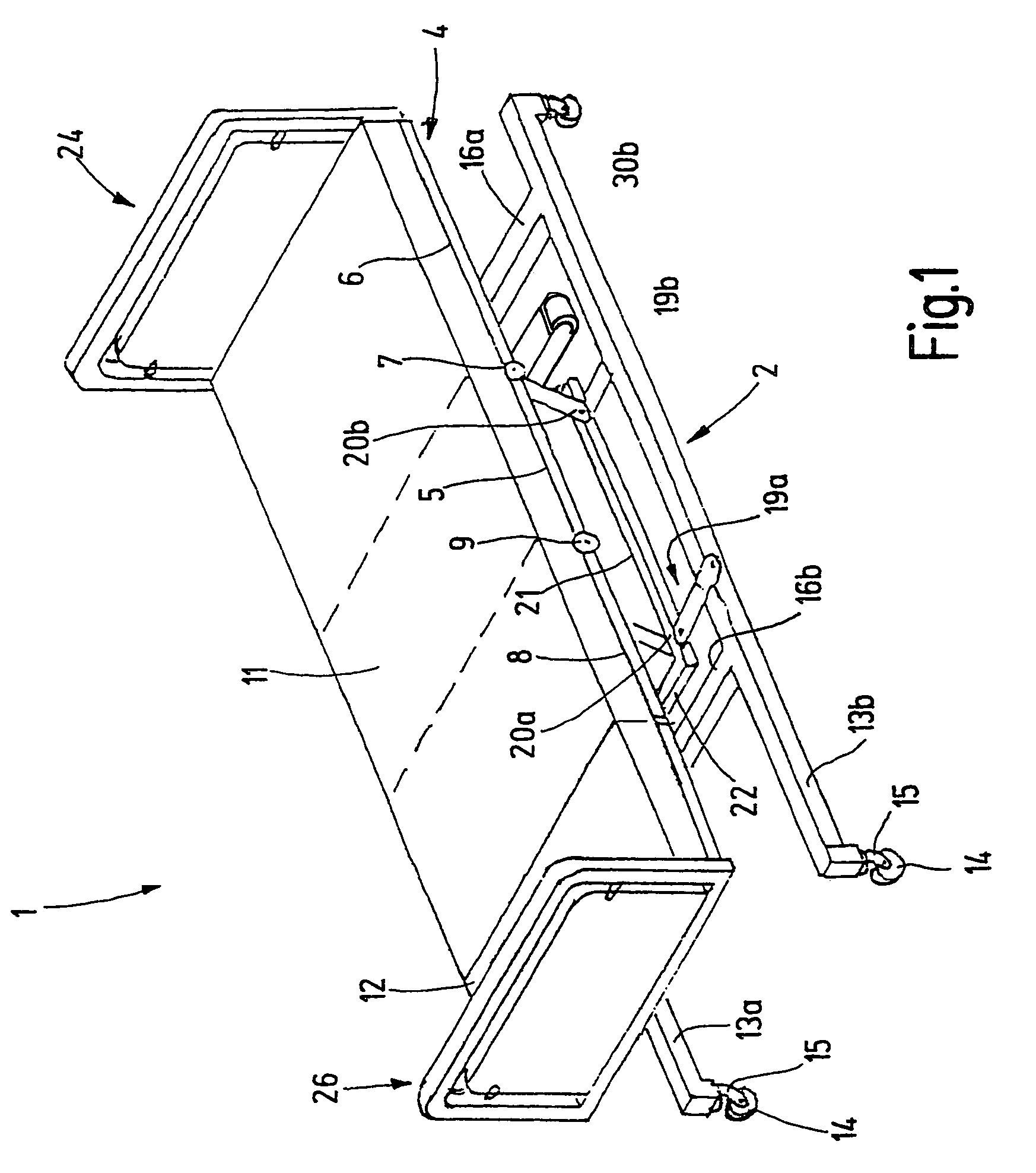
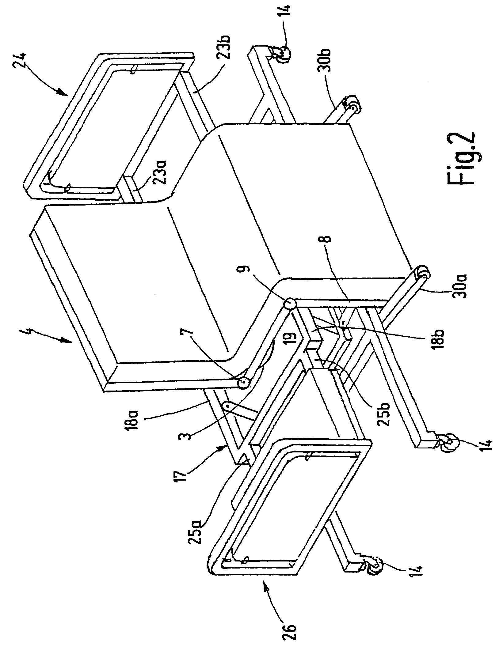
[0033]Referring now more particularly to FIGS. 1 and 2 of the drawings there is shown an illustrated rotating bed 1 embodying the present invention that is particularly adapted for use in nursing homes or hospitals. The rotating bed basically comprises a height-adjustable base 2 that stands on the floor and carries a rotary mechanisms, as depicted in FIG. 2, at its upper end. A bed frame 4 is supported on the rotary mechanism 3 for rotational movement about a vertical axis of the rotary mechanism. The bed frame 4, of which only the longitudinal rails are visible in the respective figures, is divided into at least three sections.

[0034]A center or central section 5 of the bed frame 4 is directly connected to the upper end of the base 2 by means of the rotary mechanism 3. A back section is coupled to the upper end of the central section 5 with the aid of two hinges 7 that are aligned with one another and interconnect the rails of the respective sections. The two hinges 7 make it possib...


PUM


Abstract

A rotating bed is provided that has a base with a mattress frame supported for rotation about a vertical axis. The mattress frame is divided into sections and can be converted into a chair-like configuration in one rotational position. In order to increase the stability of the arrangement in the chair position, at least one support leg is provided that either contacts the floor from the beginning or only makes contact with the floor when the stability limit without the support leg is exceeded.

Description

FIELD OF THE INVENTION[0001]The present invention relates generally to sleeping beds, and more particularly, to a sleeping bed that can be automatically converted from a normal sleeping position into a chair position.BACKGROUND OF THE INVENTION[0002]A rotating bed known from DE 199 12 937 has a height-adjustable base. The base stands freely in a conventional bed frame. A rotary joint arranged on the base serves to connect the base to a bed or mattress frame. The bed or mattress frame is frequently divided into four sections, viewed in the longitudinal direction of the bed, namely a back part or back section, a central section, a thigh section, and a lower leg section.[0003]The central section is directly connected to the base by means of the rotary joint, the axis of which extends vertically. The back section is coupled to the central section by means of a hinge arrangement with a horizontal axis, and a thigh section is similarly connected to the central section on the opposite end....

Claims


Application Information

Patent Timeline
Patent Type & Authority Patents(United States)
IPC IPC(8): A61G7/16A61G7/015A61G7/05A61G7/053A61G7/10
CPCA61G7/015A61G7/053A61G7/1067A61G7/1076A61G7/16A61G7/0528
Inventor BARTHELT, HANS-PETER
Owner BARTHELT HANS PETER
Why Eureka
Try Eureka