Adjustable gun rest apparatus

a technology of adjustable gun rests and support arms, which is applied in the direction of machine supports, building scaffolds, ammunition loading, etc., can solve the problems of many existing gun rests that have very limited adjustment capabilities, and many existing gun rests that cannot be used with a wide variety of firearms

Inactive Publication Date: 2006-08-08
DEROS MARK A
View PDF24 Cites 75 Cited by
  • Summary
  • Abstract
  • Description
  • Claims
  • Application Information

AI Technical Summary

Benefits of technology

[0015]In accordance with still another aspect of the present invention, a gun support apparatus is provided, which includes a base portion, a first link, and a second link. The first link extends along a first link axis and attached to the base portion at a proximate end of the first link. The second link extends along a second link axis and attached to the base portion at a proximate end of the second link. A distal end of the second link is attached to a distal end of the first link. An angle formed between the first link axis and the second link axis is less than 90 degrees. The second link includes a shaft portion and a knob portion. The shaft portion has a threaded end. The knob portion has a threaded hole formed therein. The threaded end of the shaft portion is adapted to mate with the threaded hole to provide a variable length for the second link. The angle formed between the first link axis and the second link axis is preferably less than about 45 degrees. In a preferred embodiment, the angle formed between the first link axis and the second link axis is about 30 degrees, for example.
[0016]In accordance with yet another aspect of the present invention, a gun support apparatus is ...

Problems solved by technology

Many existing gun rests have very limited adjustment capability.
Also, many existing gun rests cannot be used with a wide variety of firearms (e.g., pistols, rifles, long-clip magazines, machine guns).
Many existing gun rests do not allow for pivotal movement of the support arm(s) to allow for changing targets without moving the entire gun rest.
Having to move an entire gun rest while it is supporting a gun may be noisy, cumbersome, and/or disruptive to the hunt.
Although most existing gun rests provide for barrel tilt adjustments via one or more adjustable arms and/or adjustable feet, many do not provide precise or minute adjustments for fine tuning an aim on a long range target.
Also, ...

Method used


Image

  • Adjustable gun rest apparatus
  • Adjustable gun rest apparatus
  • Adjustable gun rest apparatus

Examples


first embodiment

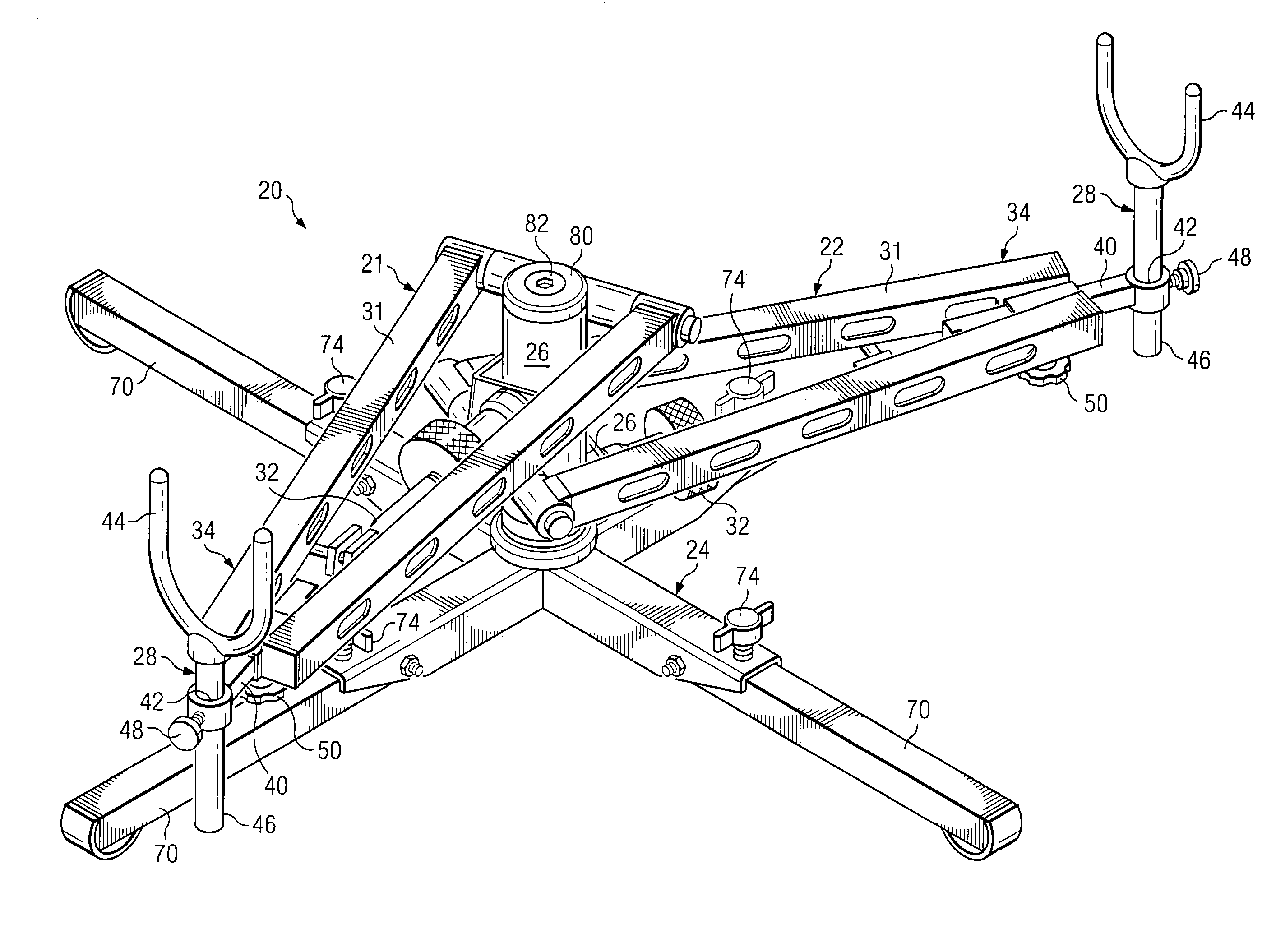
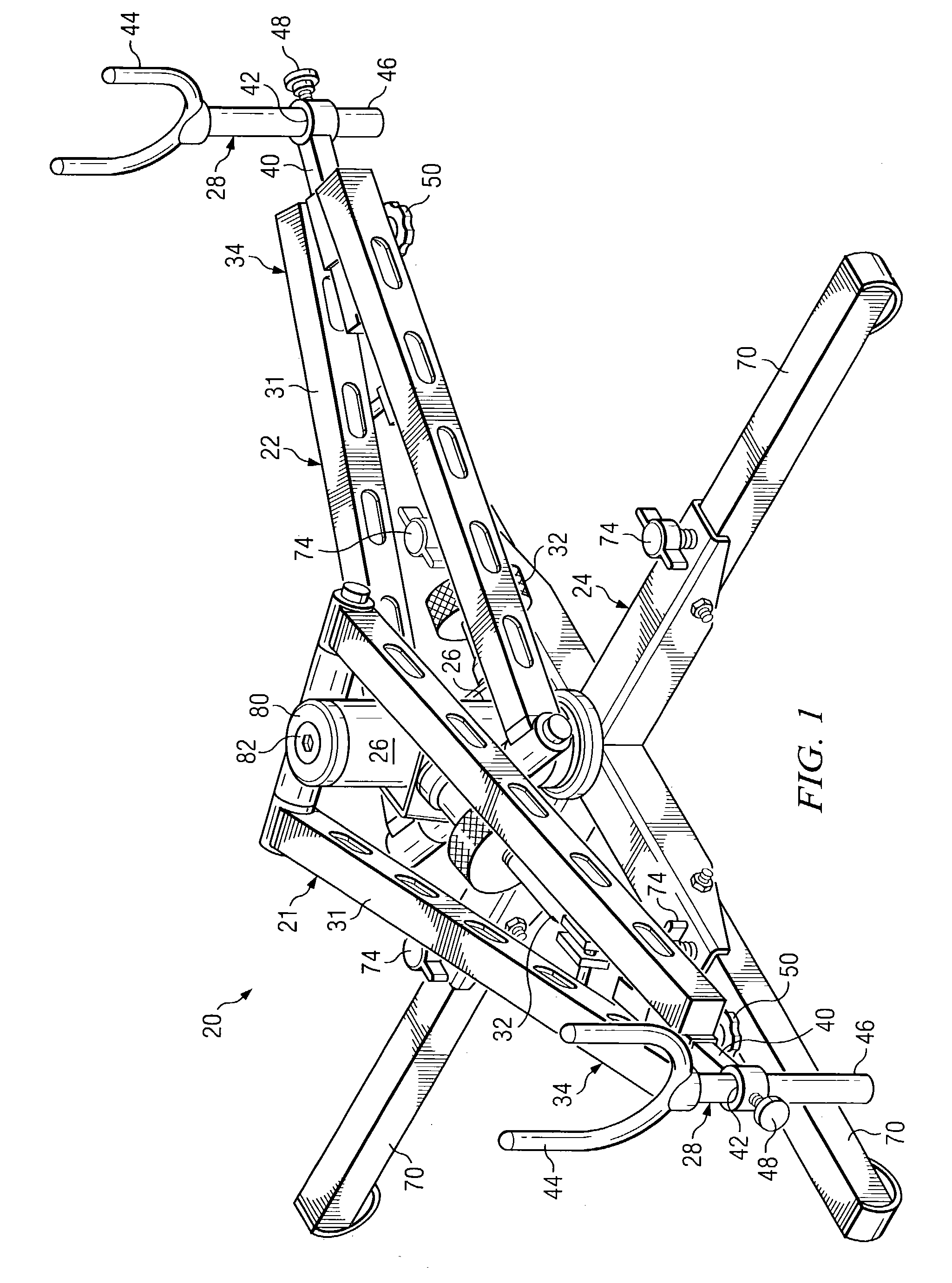
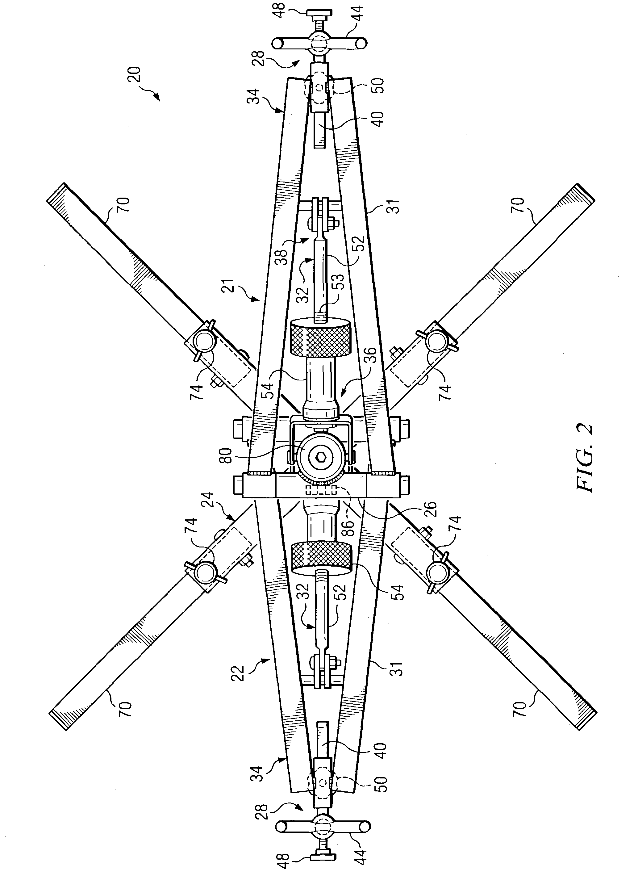
[0063]Referring to FIGS. 1 and 2, the gun rest 20 of the first embodiment has two arm members 21, 22 attached to a base portion 24. In this case, the two arm members 21, 22 are pivotably coupled to the base portion 24, as will be described in detail below. FIG. 3 is a bottom view for one of the arm members 21 from the gun rest 20 of FIGS. 1 and 2. Each arm member 21, 22 may have an upright member 26, a distal support member 28, a first link 31, and a second link 32. The first link 31 may be pivotably coupled to the upright member 26 and attached to the distal support member 28. The first link 31 may have a fixed length and may be pivotably coupled to the upright member 26 with a hinge coupling, for example. The distal support member 28 is attached to a distal end 34 of the first link 31. Hence, the first link 31 is located between the distal support member 28 and the upright member 26.

[0064]The second link 32 may be attached to the upright member 26 at a proximate end 36 of the seco...

fifth embodiment

[0080]FIG. 10 shows a gun 108 having a long clip 110 on the gun rest 20 of the One of the advantages of an embodiment of the present invention is that it may be used with guns 108 having long clips or magazines 110. Many of the prior art gun rests lack the ability and versatility to be used with guns 108 having long clips 110.

[0081]FIG. 11 shows a gun rest 20 in accordance with a sixth embodiment of the present invention. This sixth embodiment is similar to the first embodiment, except that the base portion 24 and the distal support members 28 differ. As shown in FIG. 11, the base portion 24 may have a generally plate-shaped portion 112 with mounting holes 114 formed therein. Such a base portion 24 may be bolted to another object (e.g., a table, a deer stand, a tripod, a vehicle, a boat), for example. Also in another example, such a base portion 24 may be staked to the ground (i.e., driving stakes (not shown) into the ground through the mounting holes 114).

[0082]The distal support ...

eighth embodiment

[0086]Often while hunting or in military combat scenarios, it may be desirable to shoot a gun 108 accurately from a prone position. As shown in FIG. 15, an embodiment of the present invention may be used in a prone position while still providing a stable and precise platform for the gun 108. In some situations or activities, it is desirable to get the shooter 128 and the gun 108 as low to the ground or surface 136 as possible. FIG. 16 shows the present invention, which provides the ability to position the gun 108 very close or on the ground / surface. The distal support members 28 may include generally J-shaped cradle portions 138 that extend below the first links 31 of the arm members 21, 22, as shown in FIG. 16.

[0087]FIG. 17 shows a ninth embodiment of the present invention. In the ninth embodiment, one of the distal support members 28 has a platform portion 140. As shown in the FIG. 17, this embodiment may be used for supporting a pistol 142, for example. FIG. 18 shows a tenth embo...


PUM


Abstract

A gun support apparatus is provided, which includes a base portion, a first arm member, and a second arm member. The first arm member is attached to the base portion. The second arm member is attached to the base portion. Each of the first and second arm members includes an upright member, a distal support member, a first link, and a second link. The first link is pivotably coupled to the upright member and attached to the distal support member, such that the first link is located between the distal support member and the upright member. The second link is pivotably coupled to the upright member and pivotably coupled to a distal end of the first link, such that the second link is located between the distal support member and the upright member. The second link has a variable length, and may include a dampener, spring, and/or friction element.

Description

[0001]This application claims the benefit of U.S. Provisional Application No. 60 / 400,666, filed on Aug. 2, 2002, entitled Versa Gun Rest, which application is hereby incorporated herein by reference.TECHNICAL FIELD[0002]The present invention relates to gun rests or gun support systems, and more particularly to adjustable gun rests.BACKGROUND[0003]Many existing gun rests have very limited adjustment capability. Also, many existing gun rests cannot be used with a wide variety of firearms (e.g., pistols, rifles, long-clip magazines, machine guns). For example, many existing gun rests may only be used for rifles that do not have long clips or magazines. It may be desirable to have a single gun rest capable of being used for many different sizes and shapes of firearms. It may also be desirable to have a gun rest that may also be used for other household or workshop functions, as a tool, rather than just being useful to holding certain guns. Hence, a need exists in some applications for a...

Claims


Application Information

Patent Timeline
IPC IPC(8): F41A23/02F41A23/14F41A23/16
CPCF41A23/16F41A23/02F41B5/1449
Inventor DEROS, MARK A.
Owner DEROS MARK A
Why Eureka
Try Eureka