Piston for a hydraulic brake system and master cylinder equipped therewith

a hydraulic brake and master cylinder technology, applied in the direction of braking systems, couplings, mechanical apparatuses, etc., can solve the problems of reducing the deformation ability of the sealing element, and achieve the effects of high wear resistance, rapid pressure build-up, and simple design

Active Publication Date: 2006-08-08
LUCAS AUTOMOTIVE GMBH
View PDF8 Cites 8 Cited by
  • Summary
  • Abstract
  • Description
  • Claims
  • Application Information

AI Technical Summary

Benefits of technology

[0008]An object of the present invention is to provide a piston of the initially described type which, while being of a simple design and highly resistant to wear, allows a rapid pressure build-up in the pressure chamber.

Problems solved by technology

This further reduces the deformability of the sealing element and stabilizes the sealing element as a whole.

Method used


Image

  • Piston for a hydraulic brake system and master cylinder equipped therewith
  • Piston for a hydraulic brake system and master cylinder equipped therewith
  • Piston for a hydraulic brake system and master cylinder equipped therewith

Examples


Embodiment Construction

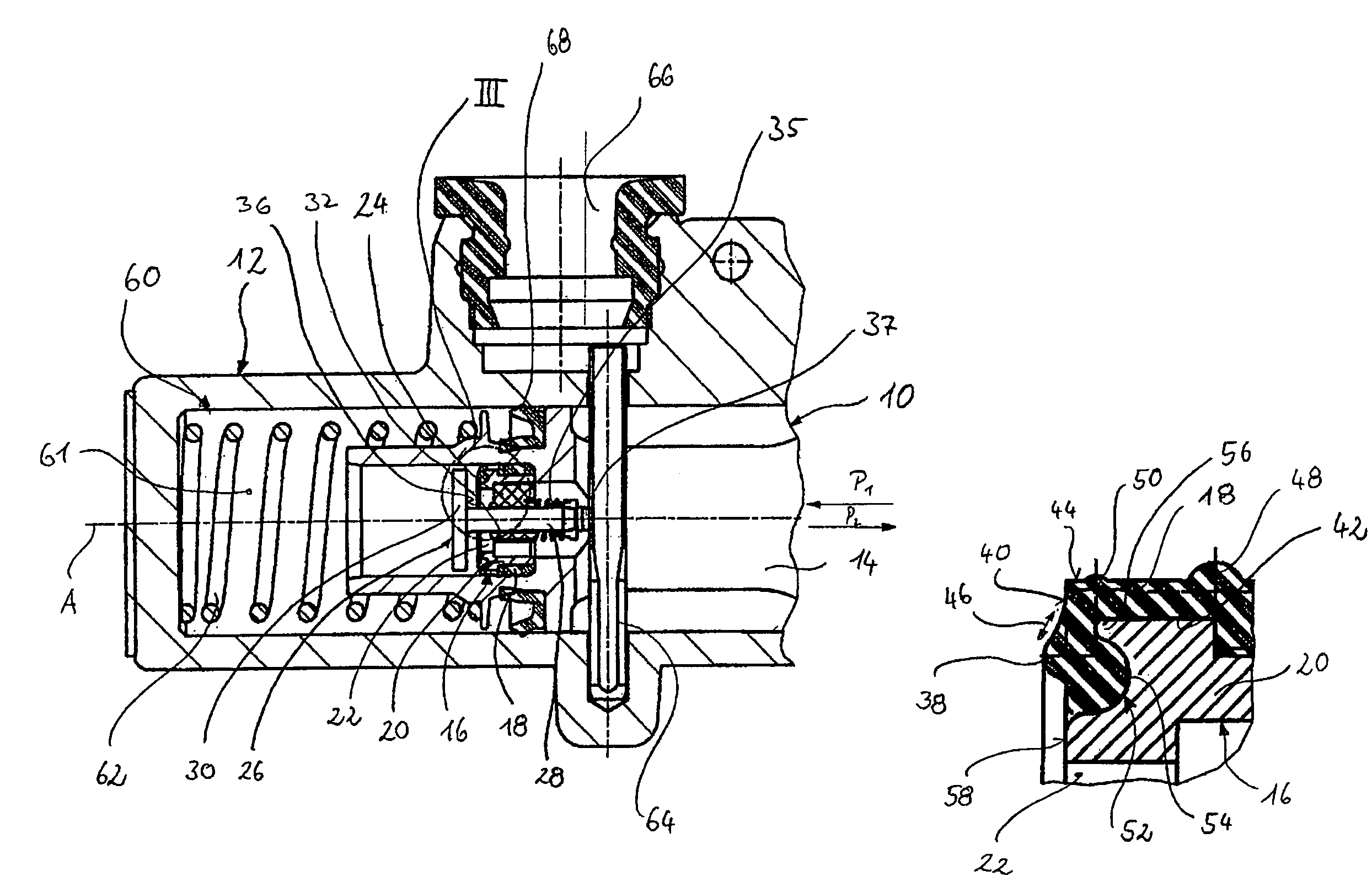
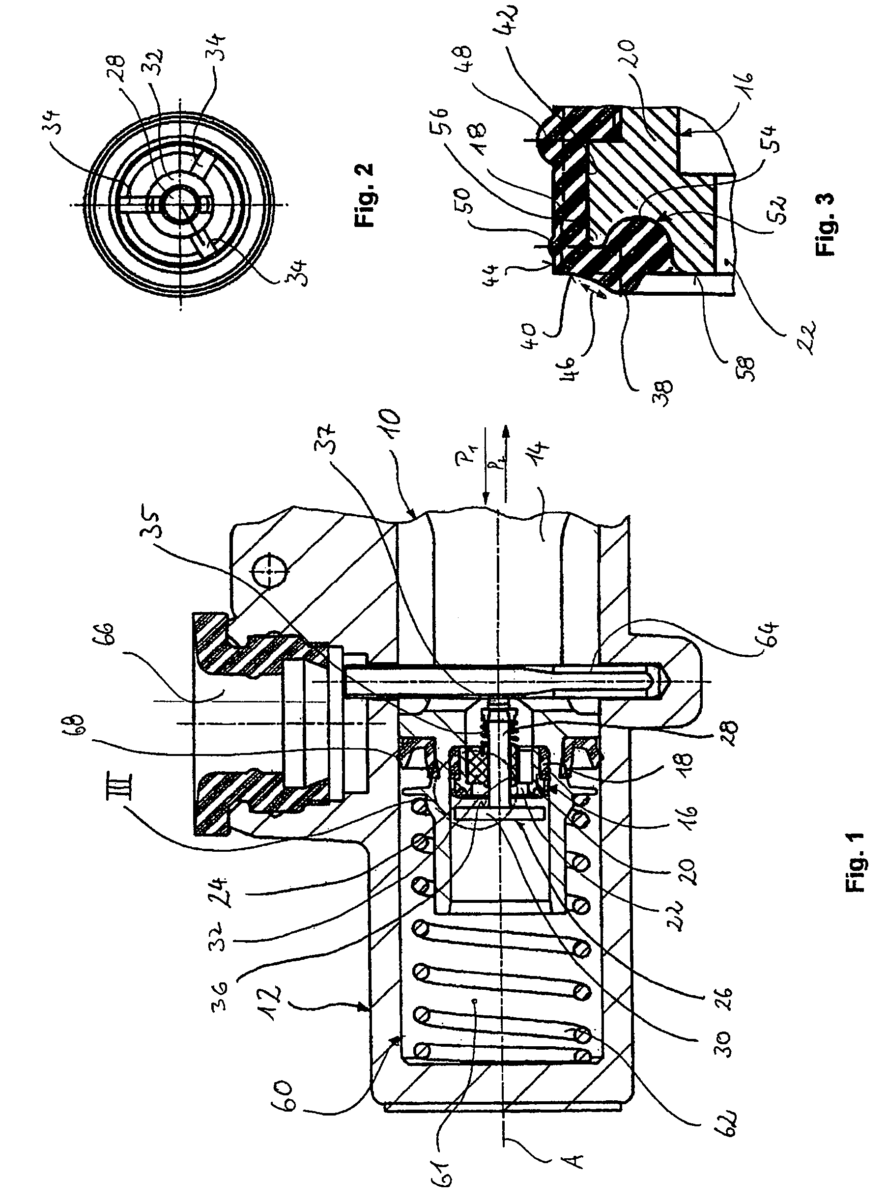
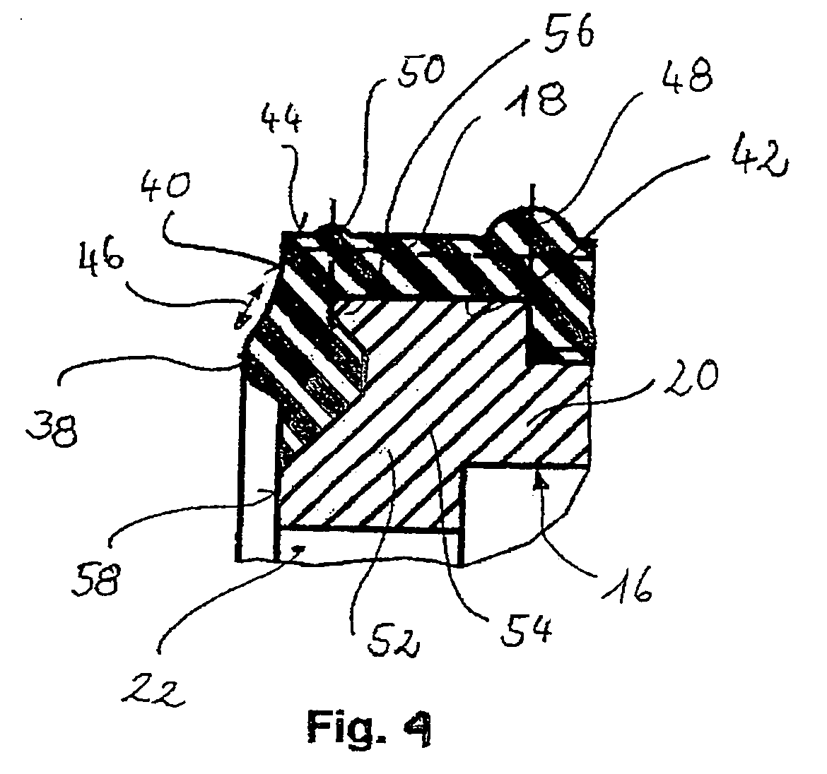
[0026]In FIG. 1, a piston according to the invention is illustrated in an axis-containing part-sectional view and generally denoted by 10. The piston 10 is guided movably in the direction of the axis A in a cylinder housing 12 of a master cylinder. The piston 10 is designed with a stepped piston channel 14, which penetrates the piston axially. A sealing component 16, comprising a sealing element 18 and a support element 20, is installed with press fit adhesion in the piston channel 14. The design of the sealing component 16 is additionally described in detail below.

[0027]The sealing component 16 is designed likewise with a central stepped through-channel 22, in which a guide element 24 is received and press-fitted such as to be locked against displacement. In the guide element 24 a valve element 26 is guided in an axially displaceable manner. The valve element 26 comprises a valve tappet 28 and a valve disc 30. For guiding the valve element 26 in the guide element 24, the valve tapp...


PUM


Abstract

The invention relates to a piston having a valve arrangement for a vehicle hydraulic brake system comprising a piston channel penetrating the piston, a valve seat formed around an opening of the piston channel, and a valve element, which is displaceable relative to the piston and which for sealing the piston channel is positionable in a fluid-tight manner against the valve seat, wherein the valve seat takes the form of an annular projection on a sealing component, which comprises an elastic sealing element and a support element, which stabilizes the sealing element, and wherein the support element is designed in a region close to the sealing projection with a corresponding annular recess.

Description

CROSS REFERENCE TO RELATED APPLICATIONS[0001]This application is a continuation of International Application No. PCT / EP03 / 13962 filed Dec. 9, 2003, the disclosures of which are incorporated herein by reference, and which claimed priority to German Patent Application No. 102 58 790.6 filed Dec. 16, 2002, the disclosures of which are incorporated herein by reference.BACKGROUND OF THE INVENTION[0002]The present invention relates to a piston with a valve arrangement for a vehicle hydraulic brake system comprising a piston channel penetrating the piston, a valve seat formed around an opening of the piston channel, and a valve element, which is displaceable relative to the piston and for sealing the piston channel is positionable in a fluid-tight manner against the valve seat, wherein the sealing seat takes the form of an annular projection on a sealing component, which comprises an elastic sealing element and a support element, which stabilizes the sealing element.[0003]Such a piston is ...

Claims


Application Information

Patent Timeline
Patent Type & Authority Patents(United States)
IPC IPC(8): B60T11/16B60T11/232F15B15/20
CPCF15B15/204B60T11/232B60T11/28
Inventor MALLMANN, MARKUSRUNKEL, DIRKCHAU, KAM
Owner LUCAS AUTOMOTIVE GMBH
Why Eureka
Try Eureka