Spray cooling system

a cooling system and spray technology, applied in the direction of domestic cooling apparatus, semiconductor/solid-state device details, lighting and heating apparatus, etc., can solve the problems of inability to meet the high thermal management requirements of today's advanced electronics with increased power density, designed for large-scale electronic systems, and unnecessary isolation and thermal management of entire circuit boards. , to achieve the effect of efficient thermal managemen

Inactive Publication Date: 2006-08-08
PARKER INTANGIBLES LLC
View PDF2 Cites 8 Cited by
  • Summary
  • Abstract
  • Description
  • Claims
  • Application Information

AI Technical Summary

Benefits of technology

[0013]In view of the foregoing disadvantages inherent in the known types of thermal management systems now present in the prior art, the present invention provides a new spray cooling system construction wherein the same can be utilized for efficiently thermally managing a single or multiple semiconductor chip package, or for thermally managing multiple separate single or multiple chip semiconductor chip packages.

Problems solved by technology

However, in benign environments, such as within an office, it is often times unnecessary to isolate and thermally manage the entire circuit boards.
The main problem with conventional combination air-cooling and advanced cooling techniques is that they sometimes cannot satisfy the high thermal management requirements of today's advanced electronics with increased power densities.
The main problem with conventional spray cooling systems is that they are designed for large-scale electronic systems.
A further problem with conventional spray cooling systems is that they are not cost effective for electronics utilized within benign environments or with reduced thermal management requirements.
While these devices may be suitable for the particular purpose to which they address, they are not as suitable for efficiently thermally managing a single or multiple semiconductor chip package.
Conventional thermal management systems either cannot satisfy the thermal management requirements of smaller modern electronics applications or are not cost effective to implement.

Method used


Image

  • Spray cooling system
  • Spray cooling system
  • Spray cooling system

Examples


Embodiment Construction

A. Overview

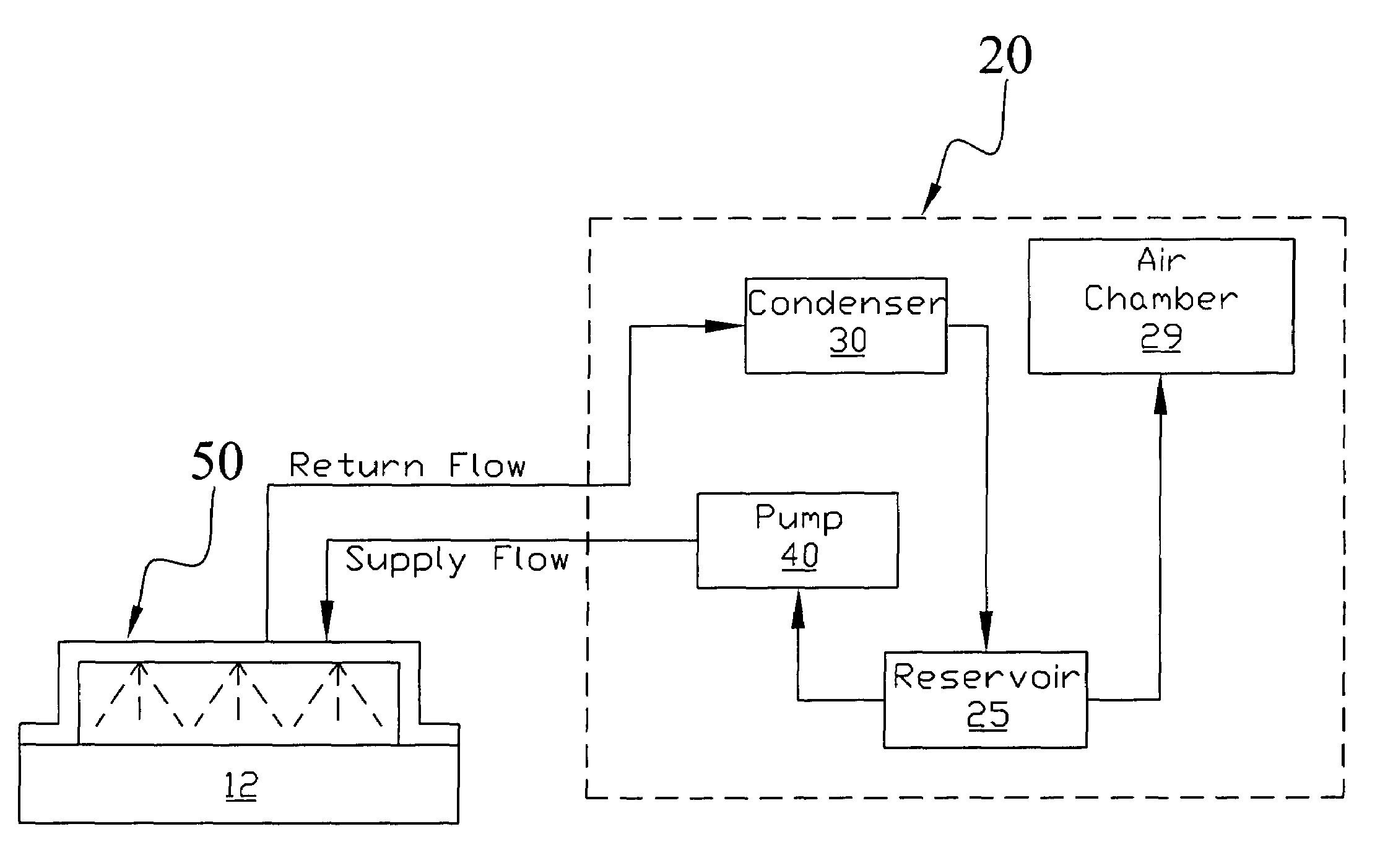
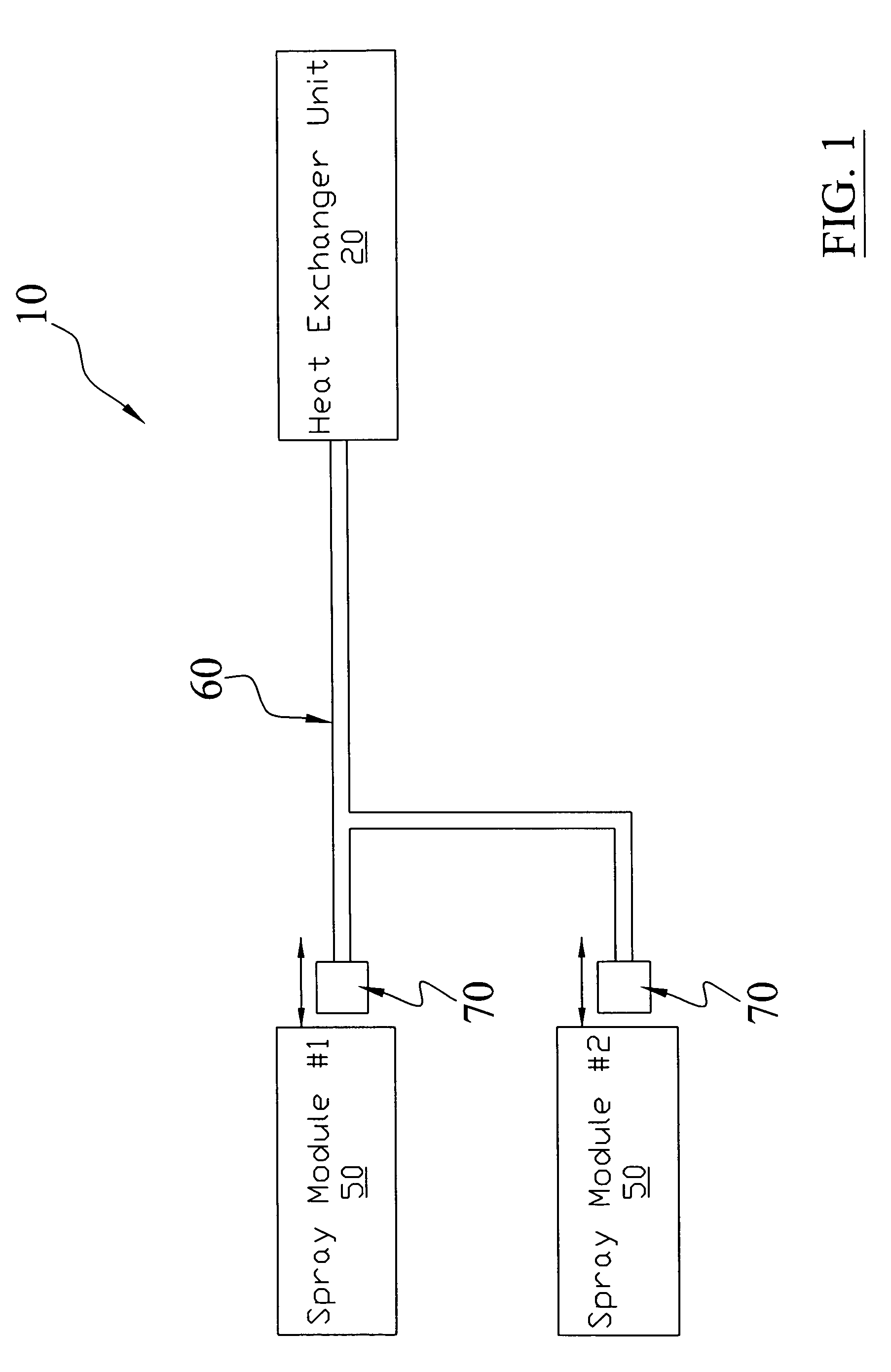
[0046]Turning now descriptively to the drawings, in which similar reference characters denote similar elements throughout the several views, FIGS. 1 through 9 illustrate a spray cooling system 10, which comprises a heat exchanger unit 20 having a pump unit 40 and a reservoir 25, a coaxial tube 60 fluidly connected to the heat exchanger unit 20, a coupler unit 70 attached to the coaxial tube 60, and a spray module 50 where the coupler unit 70 is removably connected to the spray module 50. The heat exchanger unit 20 has an air tolerant design that allows for the entry and release of air without interfering with the operation thereof.

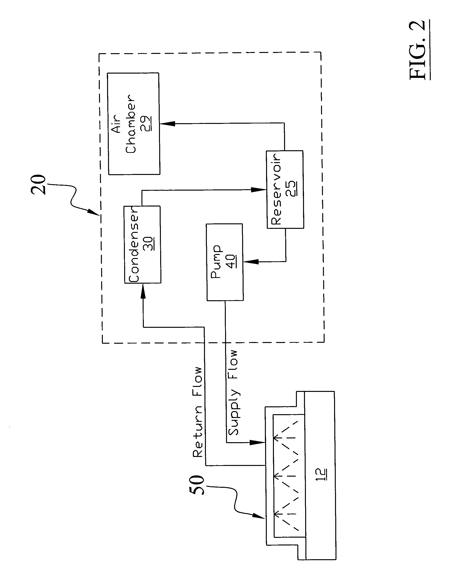
B. Heat Exchanger Unit

[0047]The heat exchanger unit 20 is a self-contained structure including a pump unit 40, a reservoir 25 and an air chamber 29 as best illustrated in FIG. 3 of the drawings. The heat exchanger unit 20 is designed to be gravity operated in various orientations and to tolerant to the entry of air and other gases into the fluid...


PUM


Abstract

A spray cooling system for efficiently thermally managing a single or multiple semiconductor chip package. The spray cooling system includes a heat exchanger unit having a pump unit and a reservoir, a coaxial tube fluidly connected to the heat exchanger unit, a coupler unit attached to the coaxial tube, and a spray module where the coupler unit is removably connected to the spray module. The heat exchanger unit has an air tolerant design that allows for the entry and release of air without interfering with the operation thereof.

Description

CROSS REFERENCE TO RELATED APPLICATIONS[0001]I hereby claim benefit under Title 35, United States Code, Section 120 of continuation-in part of U.S. patent application Ser. No. 10 / 292,073 filed Nov. 12, 2002 entitled “Integrated Circuit Heat Dissipation System” and U.S. patent application Ser. No. 10 / 368,289 filed Feb. 14, 2003. This application is a continuation-in part of the Ser. No. 10 / 368,289 application filed Feb. 14, 2003 now U.S. Pat. No. 6,889,515. The Ser. No. 10 / 368,289 application is currently pending. The Ser. No. 10 / 368,289 and Ser. No. 10 / 292,073 applications are hereby incorporated by reference into this application.STATEMENT REGARDING FEDERALLY SPONSORED RESEARCH OR DEVELOPMENT[0002]Not applicable to this application.BACKGROUND OF THE INVENTION[0003]1. Field of the Invention[0004]The present invention relates generally to spray cooling devices and more specifically it relates to a spray cooling system for efficiently thermally managing a single or multiple semiconduc...

Claims


Application Information

Patent Timeline
Patent Type & Authority Patents(United States)
IPC IPC(8): F28D15/02F25D23/12F28F7/02H01L23/433
CPCF28D5/00F28D15/0258F28D15/0266F28F7/02H01L23/4336H01L23/4735H01L2924/0002H01L2924/3011H01L2924/00
Inventor TILTON, CHARLES L.TILTON, DONALD E.BADDELEY, RYAN J.CADER, TAHIRWOS, GEORGE J.
Owner PARKER INTANGIBLES LLC
Why Eureka
Try Eureka