Localized thermal management system

a technology of thermal management system and thermal management system, applied in the direction of cooling/ventilation/heating modification, semiconductor device details, semiconductor/solid-state device details, etc., can solve the problems that conventional dry thermal management technology, air convection using fans and heat sinks, is simply not capable of efficiently thermal management modern electronics, etc., to achieve efficient thermal management

Active Publication Date: 2008-09-23
PARKER INTANGIBLES LLC
View PDF14 Cites 1 Cited by
  • Summary
  • Abstract
  • Description
  • Claims
  • Application Information

AI Technical Summary

Benefits of technology

[0009]In view of the foregoing disadvantages inherent in the lnown types of thermal management systems now present in the prior art, the present invention provides a new localized thermal management system construction wherein the same can be utilized for efficiently thermally managing a plurality of heat producing devices.
[0015]A second object is to provide a localized thermal management system for efficiently thermally managing a plurality of heat producing devices.
[0018]A further object is to provide a localized thermal management system that utilizes a plurality of thermal vias in combination with a centralized spray unit to efficiently thermally manage a plurality of heat producing devices.

Problems solved by technology

Conventional dry thermal management technology (e.g. forced air convection using fans and heat sinks) simply is not capable of efficiently thermally managing modern electronics.

Method used


Image

  • Localized thermal management system
  • Localized thermal management system
  • Localized thermal management system

Examples


Embodiment Construction

A. Overview

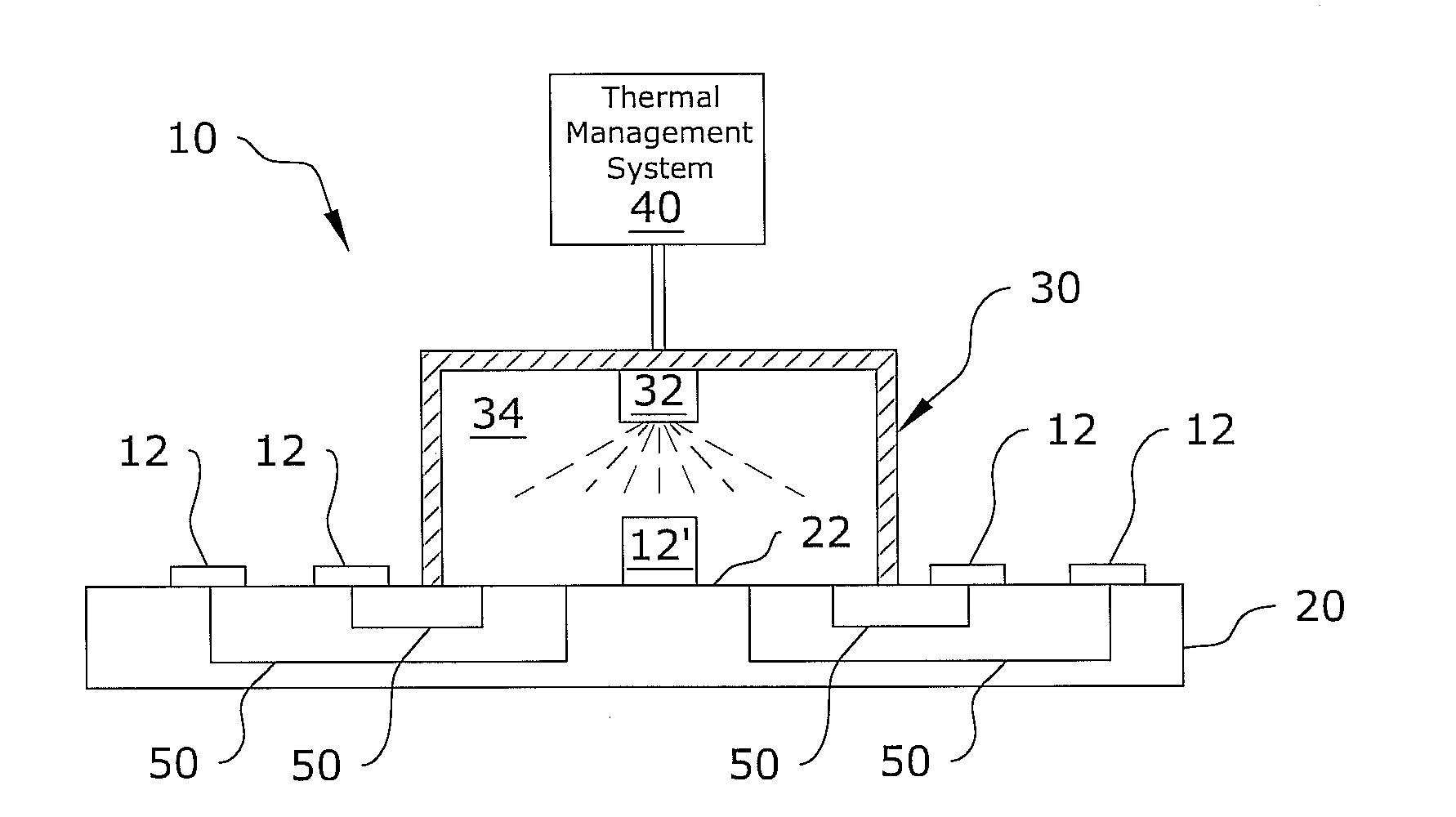
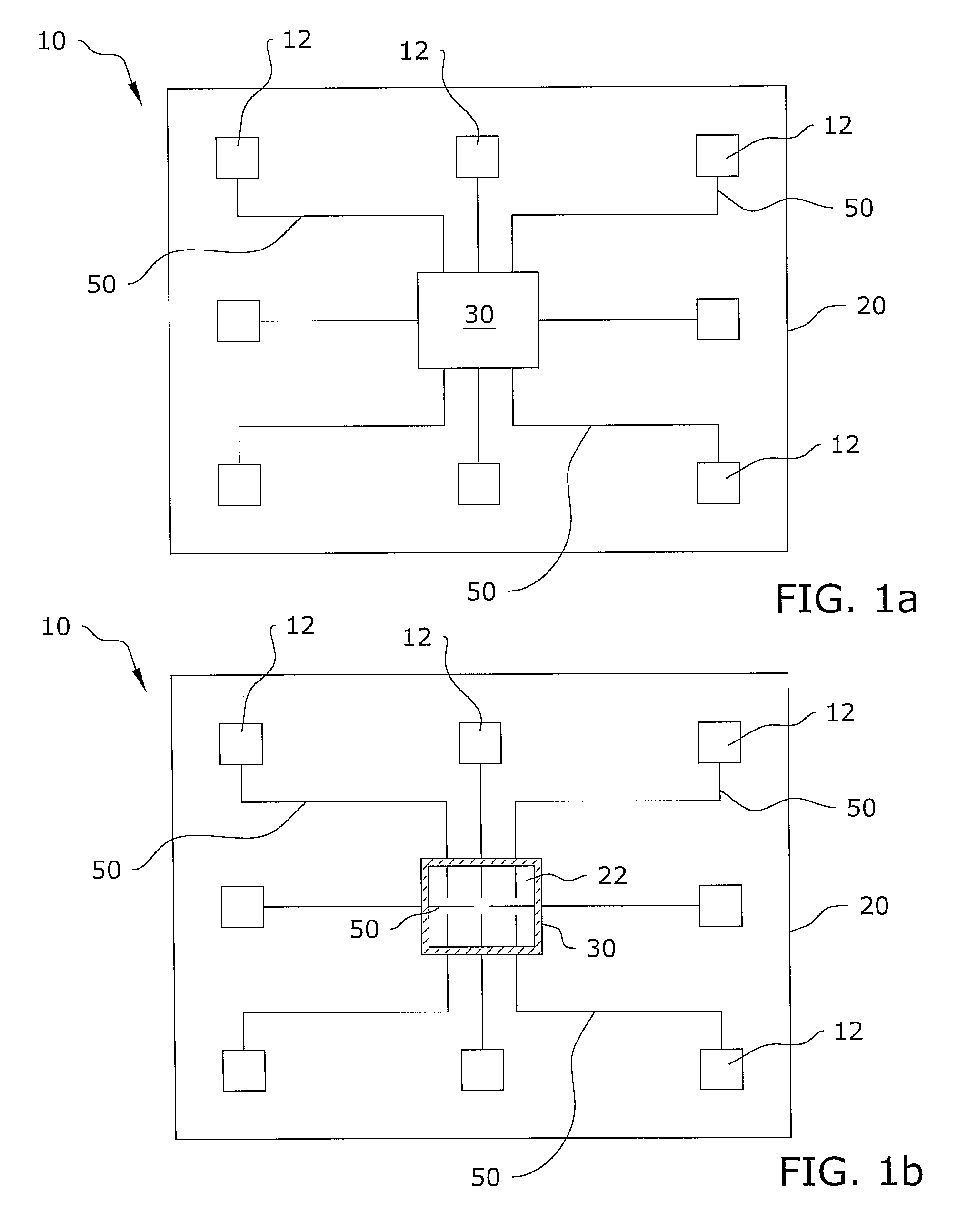
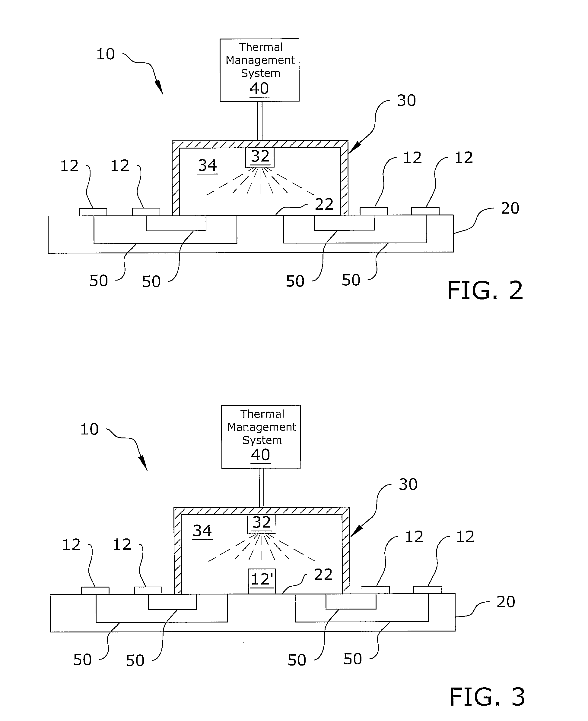
[0033]Turning now descriptively to the drawings, in which similar reference characters denote similar elements throughout the several views, FIGS. 1a through 7b illustrate a localized thermal management system 10, which comprises a thermal management unit 30 and a plurality of thermal vias 50 in thermal communication with the thermal management unit 30. The thermal vias 50 are further in thermal communication with a plurality of heat producing devices 12 for conducting heat from the heat producing devices 12 and transferring the heat to the thermal management unit 30.

[0034]FIGS. 1a through 3 illustrate a circuit board 20 with a plurality of heat producing devices 12 attached to the circuit board 20. The present invention is preferably utilized with respect to a circuit board 20 with a plurality of heat producing devices 12 (e.g. microprocessors, circuit boards 20 and power supplies), however the present invention may be implemented in various other manners and application...


PUM


Abstract

A localized thermal management system for efficiently thermally managing a plurality of heat producing devices. The localized thermal management system includes a thermal management unit and a plurality of thermal vias in thermal communication with the thermal management unit. The thermal vias are further in thermal communication with a plurality of heat producing devices for conducting heat from the heat producing devices and transferring the heat to the thermal management unit.

Description

CROSS REFERENCE TO RELATED APPLICATIONS[0001]Not applicable to this application.STATEMENT REGARDING FEDERALLY SPONSORED RESEARCH OR DEVELOPMENT[0002]Not applicable to this application.BACKGROUND OF THE INVENTION[0003]1. Field of the Invention[0004]The present invention relates generally to thermal management systems for electronic devices and more specifically it relates to a localized thermal management system for efficiently thermally managing a plurality of heat producing devices.[0005]2. Description of the Related Art[0006]Any discussion of the prior art throughout the specification should in no way be considered as an admission that such prior art is widely known or forms part of common general knowledge in the field.[0007]Modern electronic devices (e.g. microprocessors, circuit boards and power supplies) and other heat producing devices have significant thermal management requirements. Conventional dry thermal management technology (e.g. forced air convection using fans and he...

Claims


Application Information

Patent Timeline
Patent Type & Authority Patents(United States)
IPC IPC(8): H05K7/20H01L23/36
CPCH01L23/34H01L23/4735H01L2924/0002H01L2924/00
Inventor TILTON, DONALD E.
Owner PARKER INTANGIBLES LLC
Why Eureka
Try Eureka