Atomizer for thermal management system

a technology of thermal management system and atomizer, which is applied in the field of atomizers, can solve the problems of not being able to efficiently cool modern high-end electronics, not being able to direct control the coolant flow, and the fan, venting, etc., and achieves the effect of efficient thermal management on

Active Publication Date: 2008-01-01
PARKER INTANGIBLES LLC
View PDF7 Cites 1 Cited by
  • Summary
  • Abstract
  • Description
  • Claims
  • Application Information

AI Technical Summary

Benefits of technology

[0013]In view of the foregoing disadvantages inherent in the known types of atomizers now present in the prior art, the present invention provides a new atomizer for thermal management system construction wherein the same can be utilized for efficiently thermally managing one or more heat producing devices.

Problems solved by technology

Conventional dry thermal management technology (e.g. fans, vents) simply is not capable of efficiently cooling modern high-end electronics.
If the dispensed droplets do not have sufficient momentum, they will be entrained by the vapor created by the thin-film and not contribute to cooling.
If the dispensed droplets have too much momentum, they may cause splashing of the cooling surface.
One of the problems with conventional atomizers is that they do not allow for direct control of the coolant flow at the atomizer.
The distance between the valve and atomizer creates unwanted system delay.
Another problem with conventional atomizers is that the coolant flow rate through each individual atomizer is controlled solely by the pressure of the coolant.
The pressure can be controlled throughout the entire system through pump controls and valve controls; however the pressure cannot be easily controlled for each individual atomizer.
Controlling atomizer pressures creates non-optimal droplet momentums; momentums necessary for high CHF's.
Another problem with conventional atomizers is that they are typically designed for a specific application and thermal management system.
Conventional atomizers typically cannot be utilized in other thermal management system.
In addition, if the characteristics of the heat producing device are changed requiring additional or reduced thermal management in specific locations, conventional atomizers do not provide the flexibility required to adjust accordingly.
A further problem with conventional atomizers is that they emit a constant spray upon the heat producing device.
This constant spray upon the heat producing device may “flood” the surface of the heat producing device thereby reducing the thermal management efficiency during spray cooling.

Method used


Image

  • Atomizer for thermal management system
  • Atomizer for thermal management system
  • Atomizer for thermal management system

Examples


Embodiment Construction

A. Overview

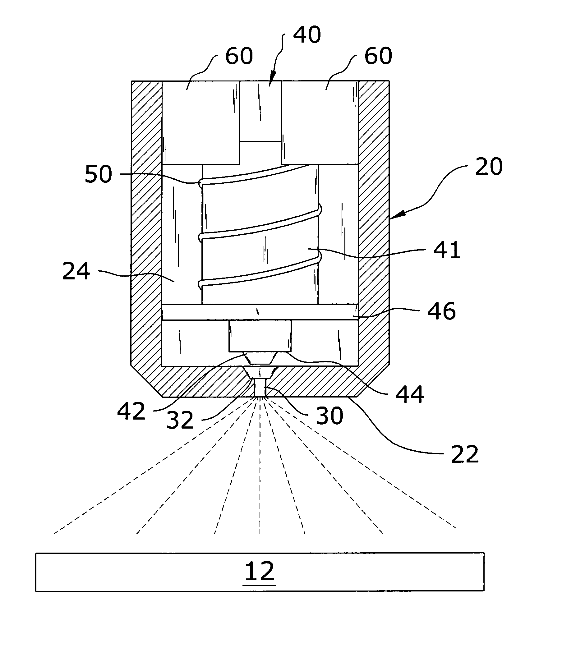
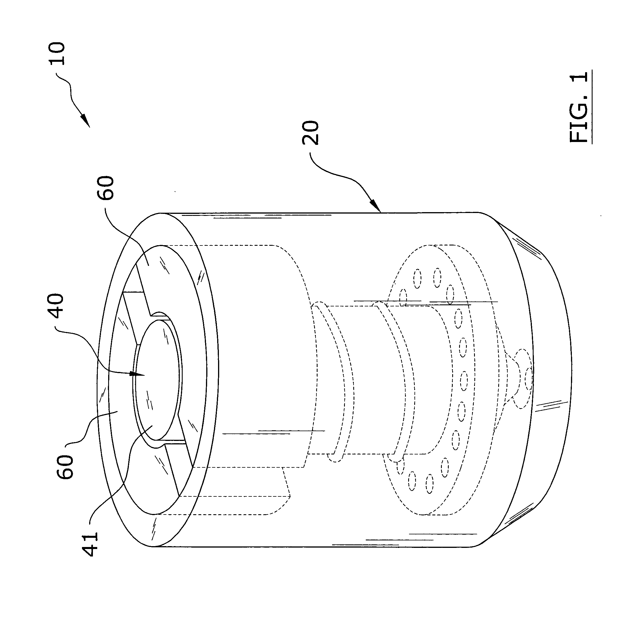
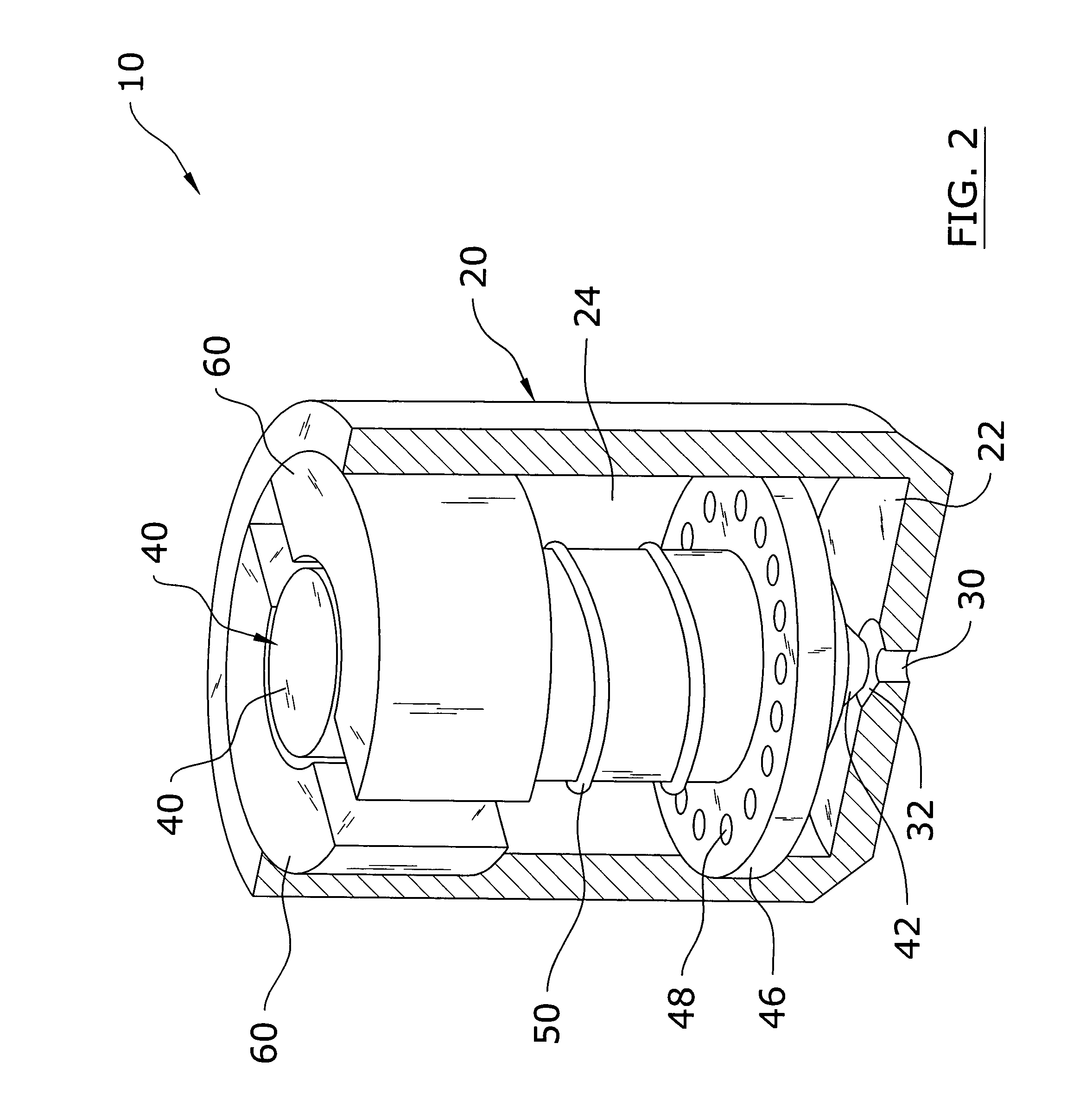
[0037]Turning now descriptively to the drawings, in which similar reference characters denote similar elements throughout the several views, FIGS. 1 through 10 illustrate an atomizer 10 for a spray cooling thermal management system. It can be appreciated that even though FIGS. 1 through 5 illustrate a single atomizer 10 that the present invention may be embodied within an atomizer array 70 wherein a plurality of atomizers 10 may be utilized as shown in FIGS. 6 through 8 of the drawings. Each atomizer 10 comprises a housing 20 having a coolant passage 24 and a dispensing end 22, an orifice 30 within the dispensing end 22, and an actuator 40 manipulating a plunger 41 within the housing 20. The plunger 41 includes a head 42 that is sealable within a recessed portion 32 of the orifice 30 to open or close the orifice 30. The coolant passes through the coolant passage 24 into the orifice 30 for spraying upon a heat producing device 12. The actuator 40 may reciprocate so that th...


PUM


Abstract

An atomizer for thermal management system for efficiently thermally managing one or more heat producing devices. The atomizer for thermal management system includes a housing having a coolant passage and a dispensing end, an orifice within the dispensing end, and an actuator manipulating a plunger within the housing. The plunger includes a head that is sealable within a recessed portion of the orifice to open or close the orifice. The coolant passes through the coolant passage into the orifice for spraying upon a heat producing device. The actuator may reciprocate so that the coolant spray emitted through the orifice is pulsating. The pulsing frequency may be increased to increase cooling or decreased to decrease cooling of the heat producing device.

Description

CROSS REFERENCE TO RELATED APPLICATIONS[0001]I hereby claim benefit under Title 35, United States Code, Section 119(e) of U.S. provisional patent application Ser. No. 60 / 475,631 filed Jun. 3, 2003. I also hereby claim benefit under Title 35, United States Code, Section 120 of U.S. patent application Ser. No. 10 / 281,391 filed Oct. 24, 2002 and U.S. patent application Ser. No. 10 / 280,240 filed Oct. 22, 2002 The 60 / 475,631, 10 / 281,391 and 10 / 280,240 applications are hereby incorporated by reference into this application.STATEMENT REGARDING FEDERALLY SPONSORED RESEARCH OR DEVELOPMENT[0002]The U.S. Government has certain rights to this invention under NASA Contract No. NAAS8-40644.BACKGROUND OF THE INVENTION[0003]1. Field of the Invention[0004]The present invention relates generally to atomizers and more specifically it relates to an atomizer for thermal management system for efficiently thermally managing one or more heat producing devices.[0005]2. Description of the Related Art[0006]Mo...

Claims


Application Information

Patent Timeline
Patent Type & Authority Patents(United States)
IPC IPC(8): F25D23/12B05B1/30
CPCB05B1/3053B05B12/06H01L23/427H01L23/4735H01L2924/0002H01L2924/00
Inventor TILTON, CHARLES L.WEILER, JEFFPALMER, RANDAL T.APPEL, PHILIP W.KNIGHT, PAUL A.
Owner PARKER INTANGIBLES LLC
Why Eureka
Try Eureka