Pad retraction spring for a brake shoe assembly and a disc brake assembly

a technology of brake shoe and retraction spring, which is applied in the direction of braking elements, actuators, slack adjusters, etc., can solve the problems of friction pads of the brake shoes wearing and becoming increasingly thin

Inactive Publication Date: 2006-08-08
KELSEY HAYES CO
View PDF28 Cites 33 Cited by
  • Summary
  • Abstract
  • Description
  • Claims
  • Application Information

AI Technical Summary

Problems solved by technology

With repeated usage, the friction pads of the brake shoes wear and become increasingly thinner.
Unfortunately, when the friction pads of the brake shoes wear thinner as described above, conventional retraction springs are typically compressed to a greater extent when the friction pads of the brake shoes are worn than when they are new.
The additional compression of known brake shoe retraction springs can result in the exertion of a force against the associated brake shoe which can overcome the roll-back seal and undesirably move the piston away from the rotor by a distance which is greater than the predetermined distance discussed above.

Method used


Image

  • Pad retraction spring for a brake shoe assembly and a disc brake assembly
  • Pad retraction spring for a brake shoe assembly and a disc brake assembly
  • Pad retraction spring for a brake shoe assembly and a disc brake assembly

Examples


first embodiment

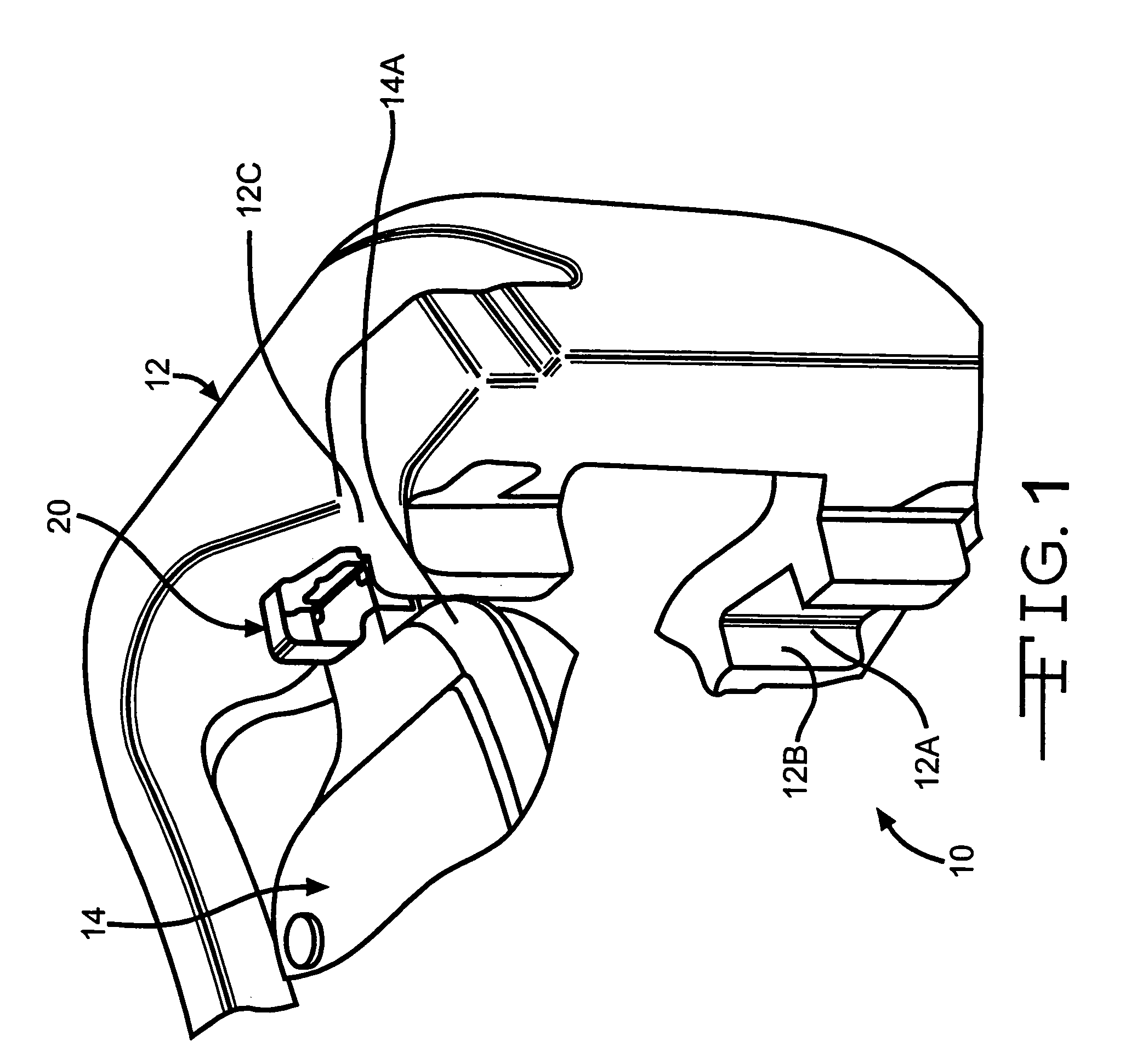
[0048]Referring now to the drawings, there is illustrated in FIG. 1 a portion of a vehicle disc brake assembly, indicated generally at 10, including a pad retraction spring or clip, indicated generally at 20, in accordance with the present invention. The general structure and operation of the vehicle disc brake assembly 10 is conventional in the art. Thus, only those portions of the vehicle disc brake assembly 10 which are necessary for a full understanding of this invention will be explained and illustrated. Although this invention will be described and illustrated in conjunction with the particular vehicle disc brake assemblies disclosed herein, it will be appreciated that this invention may be used in conjunction with other vehicle disc brake assemblies.

[0049]The disc brake assembly 10 includes an anchor plate, indicated generally at 12, having a pair of brake shoes or pad assemblies 14 (only one of such brake shoes 14 illustrated in FIG. 1), supported thereon for sliding movemen...

second embodiment

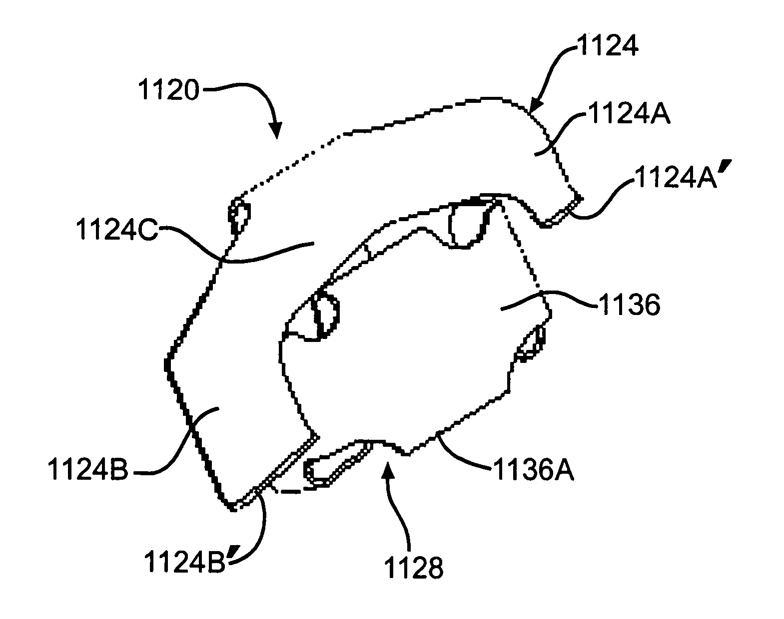
[0054]Referring now to FIGS. 4 and 5, there is illustrated a pad retraction spring, indicated generally at 120, in accordance with the present invention. As shown therein, the pad retraction spring 120 includes a first end 124, which is adapted to be operatively connected to the anchor bracket 12, and a second end 128, which is adapted to be operatively connected to an associated backing plate 14A of the brake shoe 14. In the illustrated embodiment, the first end 124 of the spring 20 is generally M or W shaped and includes a pair of protruding mounting tabs 124A and 124B and a main or center body portion 124C. The tabs 124A and 124B of the first end 124 of the spring 120 are adapted to be received in the outer recess 12A provided in the slot 12B of the anchor bracket 12. In particular, the tabs 124A and 124B are necked down and define respective shoulders 124A′ and 124B′ along the remote ends thereof. The shoulders 124A′ and 124B′ are adapted to engage the side walls of the recess 1...

third second embodiment

[0057]Referring now to FIGS. 6 and 7, there is illustrated a pad retraction spring, indicated generally at 220, in accordance with the present invention. As shown therein, the pad retraction spring 220 includes a first end 224, which is adapted to be positioned adjacent a surface 12C of the anchor bracket 12 so as to react thereagainst (the surface 12C shown in FIG. 1), and a second end 228, which is adapted to be operatively connected to an associated backing plate 14A of the brake shoe 14.

[0058]In the illustrated embodiment, the first end 224 of the spring 220 is generally U shaped and includes a pair of protruding tabs 224A and 224B extending from a main or center body portion 224C. In particular, the tabs 224A and 224B are angled or bent back relative to the main body portion 224C and are provided with respective tapered outer side wall portions 224A′ and 224B′. The second end 228 of the spring 20 includes a generally flat portion 228A and a curled over outermost end portion 228...


PUM


Abstract

This invention relates to a pad spring for use in a disc brake assembly. According to one embodiment of the present invention, the disc brake assembly comprises an anchor bracket adapted to be secured to a vehicle component; a brake caliper adapted to be secured to the anchor bracket; an inboard friction pad and an outboard friction pad carried by the disc brake assembly and adapted to be disposed on opposite axial sides of an associated brake rotor; actuation means for selectively moving the inboard and outboard friction pads into frictional engagement with the rotor; and a pad spring carried by at least one end of one of the friction pads for moving the friction pads from engagement with the rotor when the actuation means is released; wherein the pad spring includes a first portion for applying a first retraction force and a second portion for applying a second retraction force which is different from the first retraction force.

Description

CROSS-REFERENCE TO RELATED APPLICATIONS[0001]This application is a continuation of PCT / US02 / 30539, filed Sep. 25, 2002, which claims the benefit of U.S. Provisional Application Ser. No. 60 / 324,705, filed Sep. 25, 2001.BACKGROUND OF THE INVENTION[0002]This invention relates in general to vehicle disc brake assemblies and in particular to an improved structure for a pad spring for a brake shoe assembly adapted for use in such a vehicle disc brake assembly.[0003]Most vehicles are equipped with a brake system for retarding or stopping movement of the vehicle in a controlled manner. A typical brake system for an automobile or light truck includes a disc brake assembly for each of the front wheels and either a drum brake assembly or a disc brake assembly for each of the rear wheels. The brake assemblies are typically actuated by hydraulic or pneumatic pressure generated when an operator of the vehicle depresses a brake pedal. The structures of these drum brake assemblies and disc brake as...

Claims


Application Information

Patent Timeline
Patent Type & Authority Patents(United States)
IPC IPC(8): F16D65/40F16D65/097F16D65/14
CPCF16D65/0977F16D2127/02
Inventor WEMPLE, JONATHANTRAUB, GEORGE
Owner KELSEY HAYES CO
Why Eureka
Try Eureka