Buffer device for a slide structure

a buffer device and slide technology, applied in the direction of drawers, furniture parts, domestic applications, etc., can solve the problems of different elastic effects, difficult control or measurement of tightness, different elastic pressure force, etc., and achieve the effect of more solid and reliabl

Active Publication Date: 2006-08-08
KING SLIDE WORKS CO LTD
View PDF10 Cites 30 Cited by
  • Summary
  • Abstract
  • Description
  • Claims
  • Application Information

AI Technical Summary

Benefits of technology

[0010]It is the primary objective of the present invention to provide a buffer device for a slide structure, which is steady and secure.
[0011]It is another objective of the present invention to provide a buffer device for a slide structure, which can sustain the striking force.
[0012]It is a further objective of the present invention to provide a buffer device for a slide structure, which is more solid and reliable.

Problems solved by technology

This causes differential of the elastic pressure force, and is difficult to control or to measure the tightness.
This prior art causes different elastic effects and is hard to get a precise measurement.

Method used


Image

  • Buffer device for a slide structure
  • Buffer device for a slide structure
  • Buffer device for a slide structure

Examples


Embodiment Construction

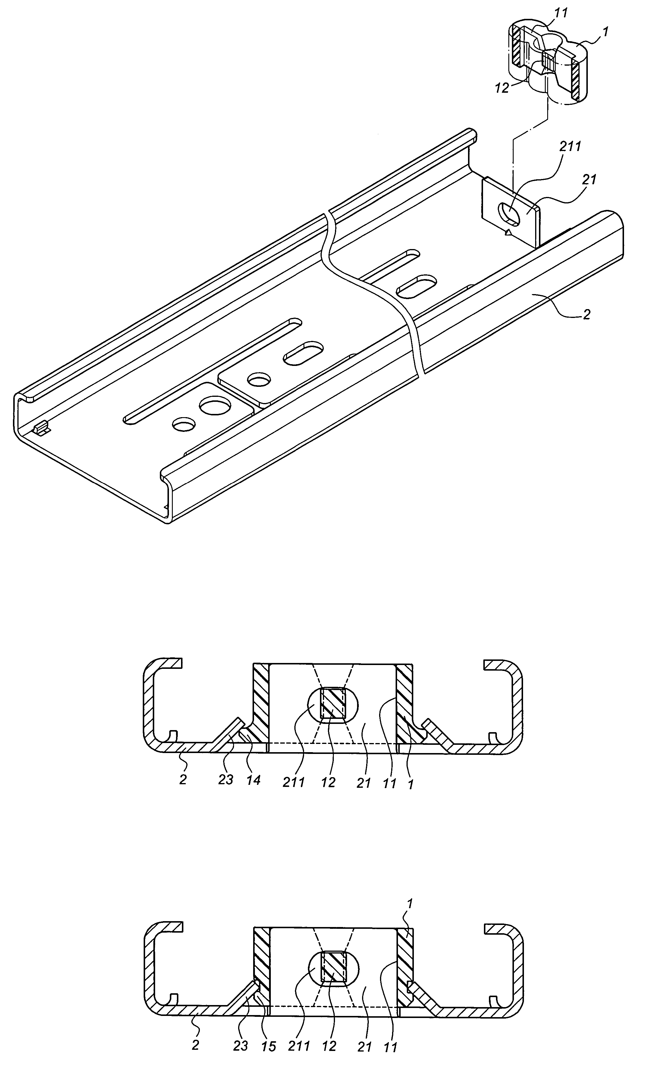
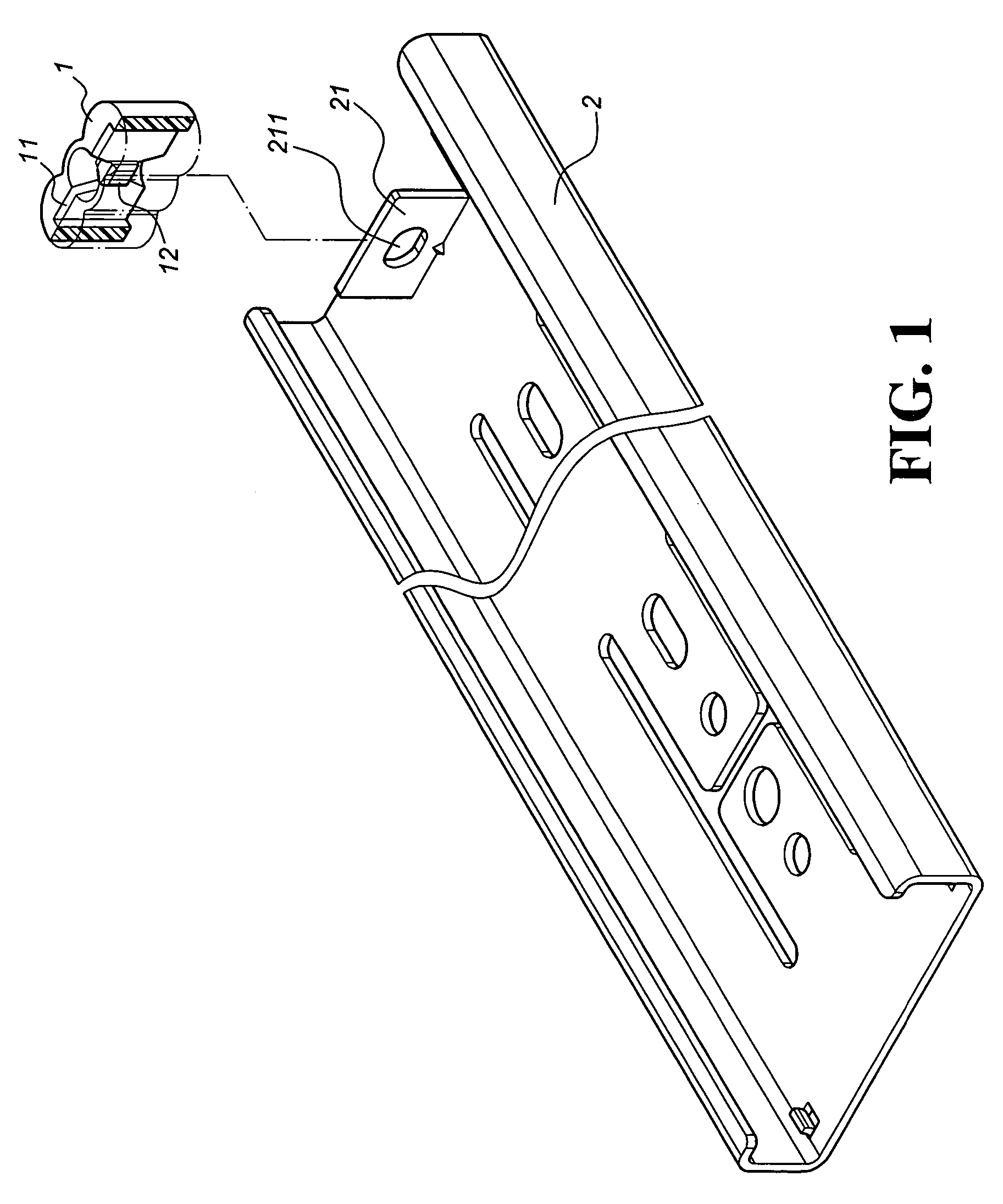
[0021]As shown in FIG. 1, a buffer device for a slide structure of the present invention comprises a buffer 1 secured to the rear end of a fixed track 2. The fixed track 2 has a plate 21 extending perpendicularly from the rear end for the buffer 1 to sleeve thereon.

[0022]The buffer 1 comprises a slot 11 having two flat ends. Two ends of the buffer 1 have the same width in cross-section. The buffer 1 further comprises a protuberance 12 protruding from an inner side at the center portion of the slot 11.

[0023]The plate 21 extending perpendicularly from the rear end of the fixed track 2 has two even sides and a hole 211 formed at the center for the protuberance 12 to insert therein.

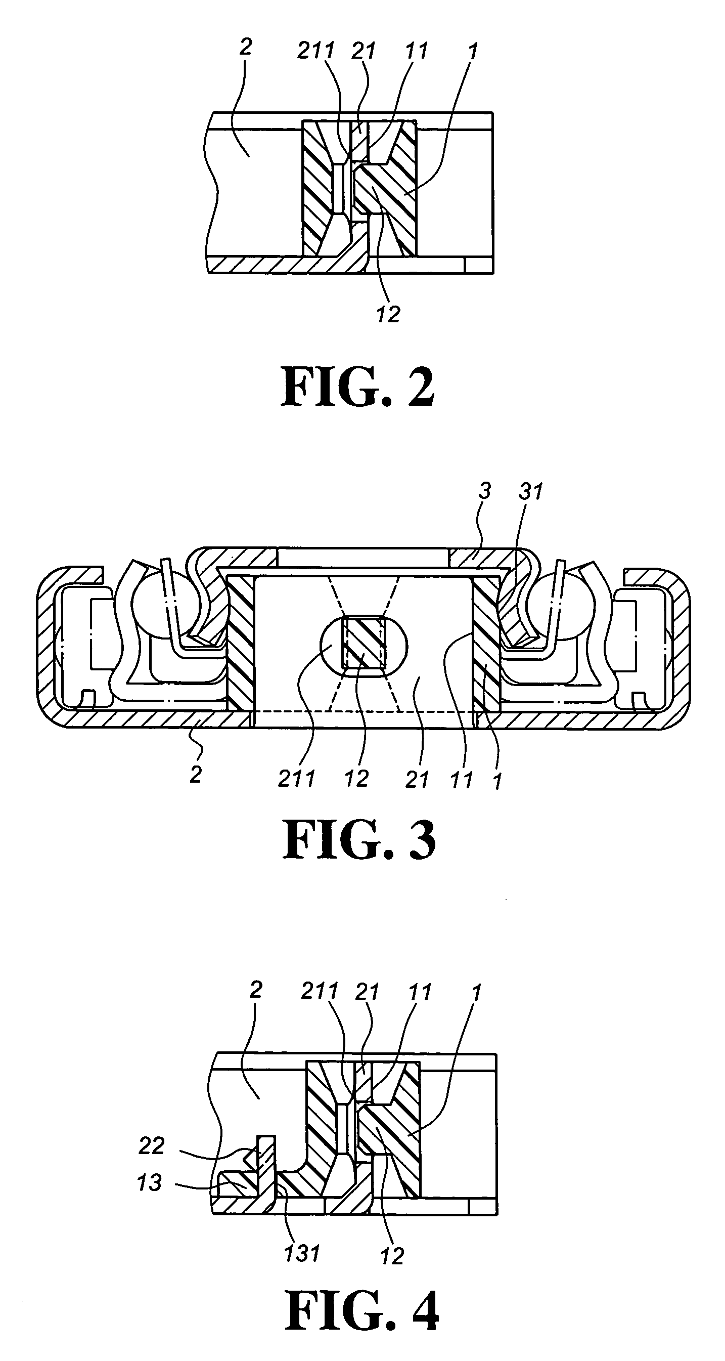
[0024]To assemble the present invention, as shown in FIG. 2, the buffer 1 is deposed onto the plate 21 of the fixed track 2 through the slot 11 so that the two are evenly connected with the protuberance 12 inserting into the hole 211 of the plate 21. The buffer 1 has a steady elastic force at respective two e...


PUM


Abstract

A buffer device for a slide structure includes a buffer secured to the rear end of a fixed track to provide a buffer effect. The buffer provides a steady elastic force when in contact with a mobile track to maintain a steady and stable status. The buffer comprises a slot at the center portion to be sleeved onto a plate extending from the rear end of the fixed track to provide an elastic force when striking by the mobile track.

Description

BACKGROUND OF THE INVENTION[0001]1. Field of the Invention[0002]This invention relates to a buffer device for a slide structure, and more particularly to a track with a buffer device installed to the rear end of a fixed track to release the striking force from a mobile track against the fixed track.[0003]2. Description of the Prior Art[0004]Slides have been widely used by users. A conventional slide includes a fixed track, a middle track and a mobile track. Taking the slide adapted to a cabinet and its drawers for example, the fixed track is secured to each inner side of the closet, while the mobile track is secured to each side of the drawer. The middle track is secured to the fixed track through ball bearings in a slidable manner to carry the mobile track. As shown in FIG. 8, a prior art comprises a mobile track A, a middle track B and a fixed track C. The mobile track A and the middle track B are connected with an axially sliding part D. The middle track B and the fixed track C a...

Claims


Application Information

Patent Timeline
Patent Type & Authority Patents(United States)
IPC IPC(8): A47B88/04
CPCA47B88/04A47B2210/0094A47B2210/0018A47B88/477
Inventor TSENG, I-MINGCHEN, KEN-CHINGWANG, CHUN-CHIANG
Owner KING SLIDE WORKS CO LTD
Why Eureka
Try Eureka