Apparatus for controlling laneway bottom heave

A technology of roadway and bottom sill, which is applied in the installation of bolts, mining equipment, earthwork drilling and mining, etc. It can solve the problems of bottom beam failure and heavy workload, and achieve the effect of simple bottom beam, reduced bottom sill, and high reliability

Inactive Publication Date: 2009-01-21
HENAN POLYTECHNIC UNIV
View PDF0 Cites 11 Cited by
  • Summary
  • Abstract
  • Description
  • Claims
  • Application Information

AI Technical Summary

Problems solved by technology

When metal bottom beams are used to strengthen the bottom slab, the bottom beam generally adopts a reverse arch shape. This method is currently only used for metal brackets

Method used


Image

  • Apparatus for controlling laneway bottom heave

Examples


Embodiment Construction

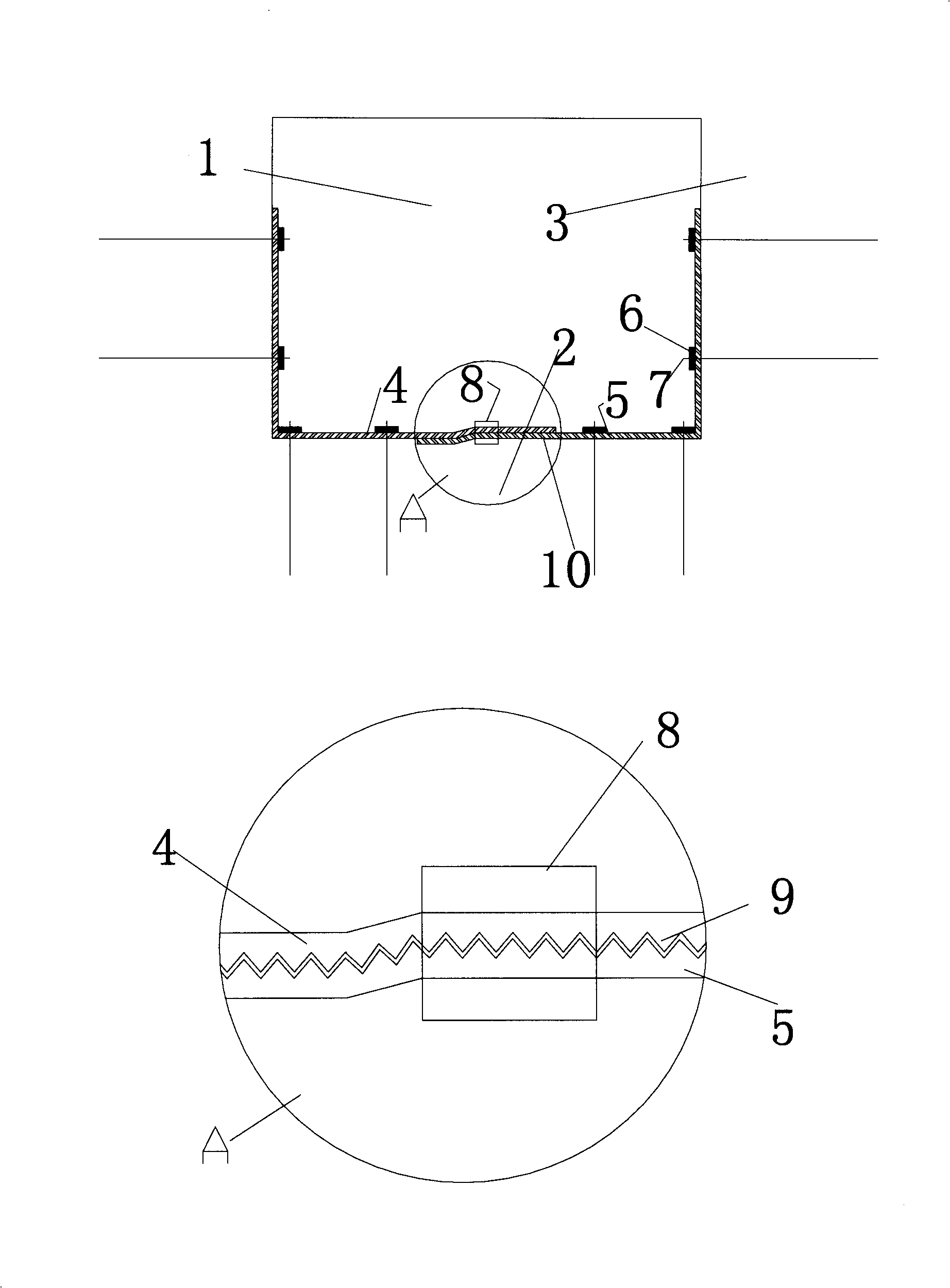
[0013] As shown in the accompanying drawings, the present invention includes a roadway 1 base plate 2 and two gangs 3 anchor rods 7, anchor rod 7 pallets 6, steel belts 4, 5 with teeth 9 and round holes and long strip holes, and a constant force clamping device 8 , The steel strips 4, 5 and the constant force clamping device together constitute the bottom beam 10. When the bottom plate 2 of the roadway 1 bulges under various factors, the bottom plate 2 provides an upward force on the bottom beam 10. Under the fixing action of the side 3 of the roadway 1 and the anchor rod 7 at the bottom corner, the steel belt 4 with teeth 9 and holes , 5 by tension. Under the action of the constant force clamping device 8, a certain friction force is generated between the steel strips 4 and 5. When the tensile force on the steel strips 4 and 5 is greater than the friction force between the steel strips 4 and 5, the steel strip 4 and the steel strip 5 The tooth slots at the overlapping place ...


PUM


Abstract

The invention relates to a device for controlling floor bulging of a roadway, which comprises a roadway floor, rock bolts on two sides of the roadway, a tray for the rock bolts, a steel band (1) and a steel band (2) with teeth and holes, and a constant force clamp device. The steel band (1), the steel band (2) and the constant force clamp device form a floor beam together. When the floor bulges of the roadway due to various factors, the floor provides an upward acting force for the floor beam, and the steel band (1) and the steel band (2) with the teeth and holes are subjected to a tensile force under the fixation of the roadway side and the base angle rock bolts. Under the action of the constant force clamp device, friction force with certain size is produced between the steel band (1) and the steel band (2). When the tensile force received by the steel bands is larger than the maximum friction force between the steel band (1) and the steel band (2), two tooth sockets at the overlapped position are dislocated to improve the length of the floor beam; when the tensile force received by the steel bands is smaller than the maximum friction force between the steel band (1) and the steel band (2), the device is in a temporary stable status. For continuous floor bulging, the device repeats the process and the dislocation of the tooth sockets between the steel band (1) and the steel band (2) improves the length of the floor beam to provide certain supporting resistance for the floor. The device applies basically constant supporting resistance to the roadway floor all the time to reduce the floor bulging amount of the roadway and have the function of reducing the overall deformation amount of the roadway.

Description

technical field [0001] The invention relates to a device for roadway undercut, which can be used for the prevention and treatment of underground roadway undercut caused by various factors, and is also suitable for controlling underground space in water conservancy, civil air defense and other projects. Background technique [0002] With the increase of coal mine mining depth, some mine roadways present significant plastic deformation and failure characteristics of large deformation, large ground pressure, and difficult support. Many roadway roof and floor strata show soft rock characteristics, which often lead to serious roadway bottoming and increase roadway damage. Convergence rate. Field surveys show that in deep roadways with unsupported floors, 2 / 3 to 3 / 4 of the approach of the roof and floor is caused by the bottom sill, and the roadway maintenance caused by the bottom slab accounts for about 50% of the total maintenance. Generally speaking, there are two methods of f...

Claims


Application Information

Patent Timeline
IPC IPC(8): E21D21/00
Inventor 郭保华田采霞
Owner HENAN POLYTECHNIC UNIV
Why Eureka
Try Eureka