Outside-in flow engine and transmission filter and method

a technology of transmission filter and inside-out flow, which is applied in the direction of filtration of dispersed particles, combination devices, gymnasium, etc., can solve the problems of insufficient utilization of media area, difficult integration of media bags with inside-out flow schemes into some transmission filter designs, and ineffective inside-out flow transmission filters

a technology of transmission filter and inside-out flow, which is applied in the direction of filtration of dispersed particles, combination devices, gymnasium, etc., can solve the problems of insufficient utilization of media area, difficult integration of media bags with inside-out flow schemes into some transmission filter designs, and ineffective inside-out flow transmission filters

US7087160B2Active Publication Date: 2006-08-08FILTRAN LLC

Image

  • Outside-in flow engine and transmission filter and method
  • Outside-in flow engine and transmission filter and method
  • Outside-in flow engine and transmission filter and method

Examples


Embodiment Construction

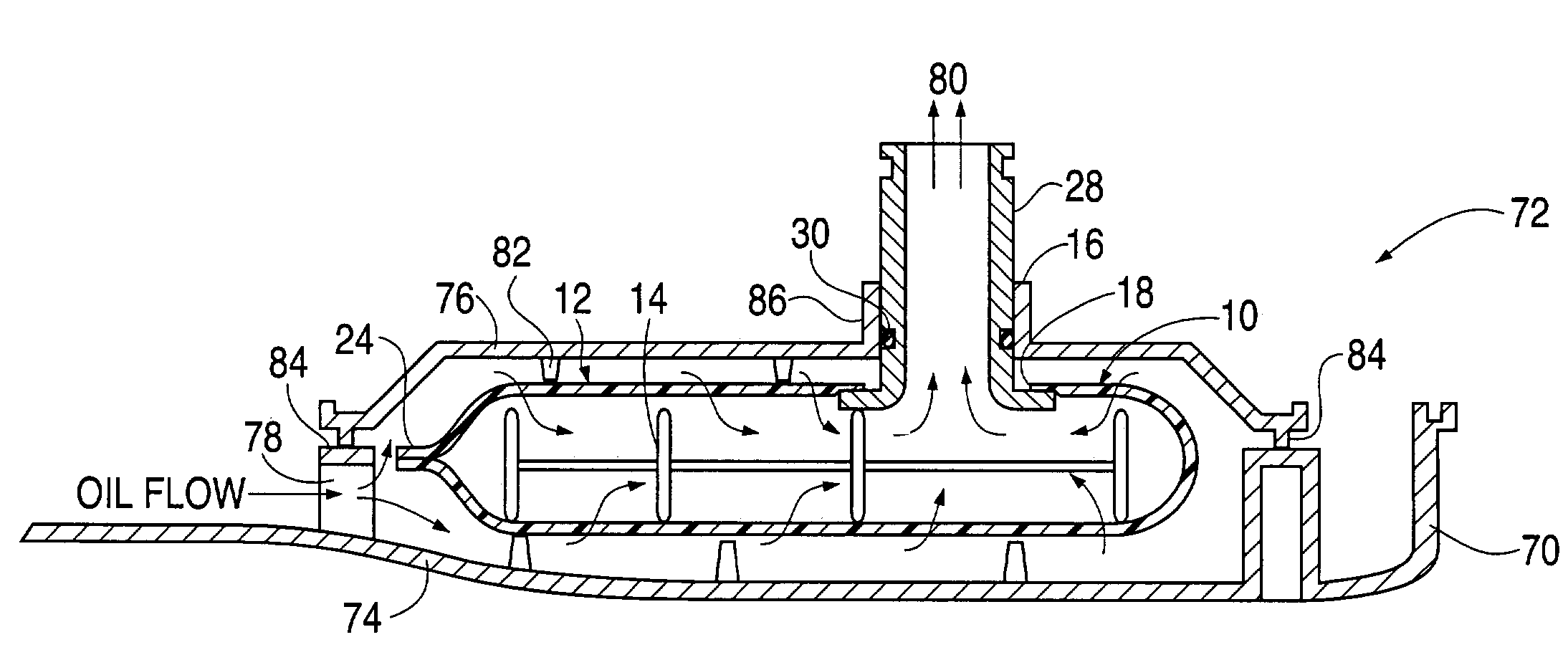
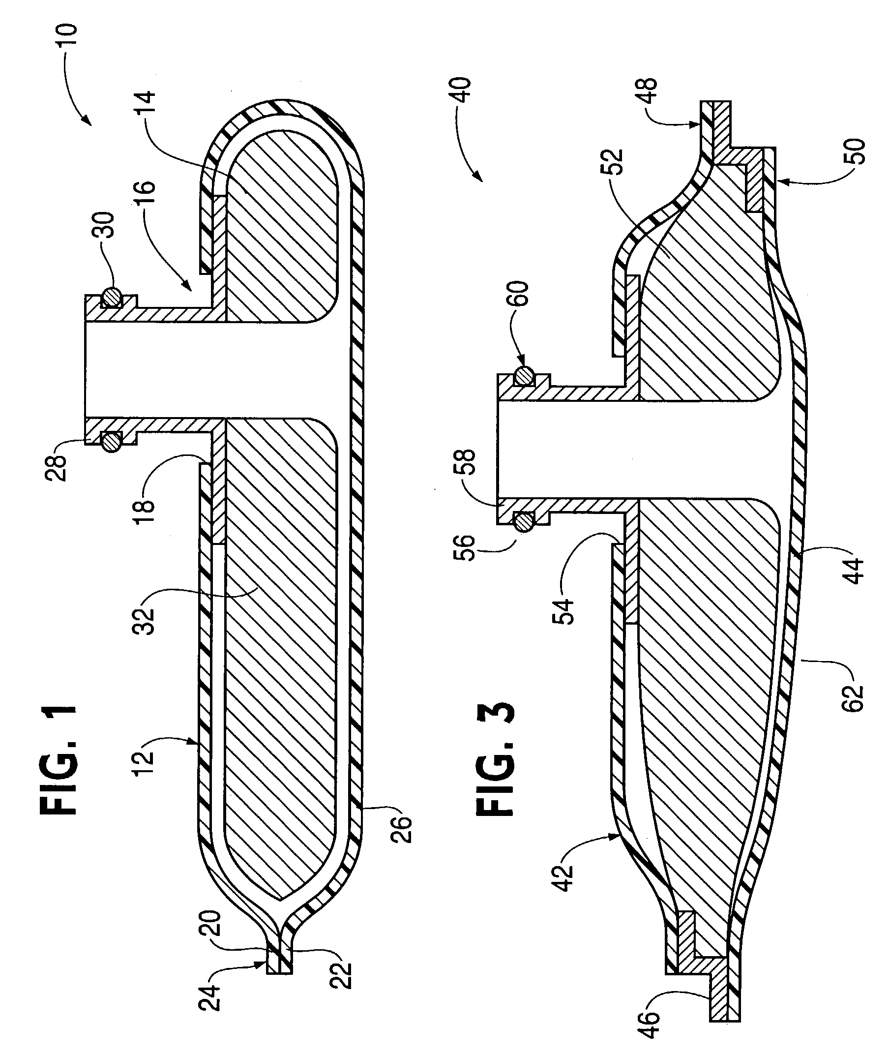
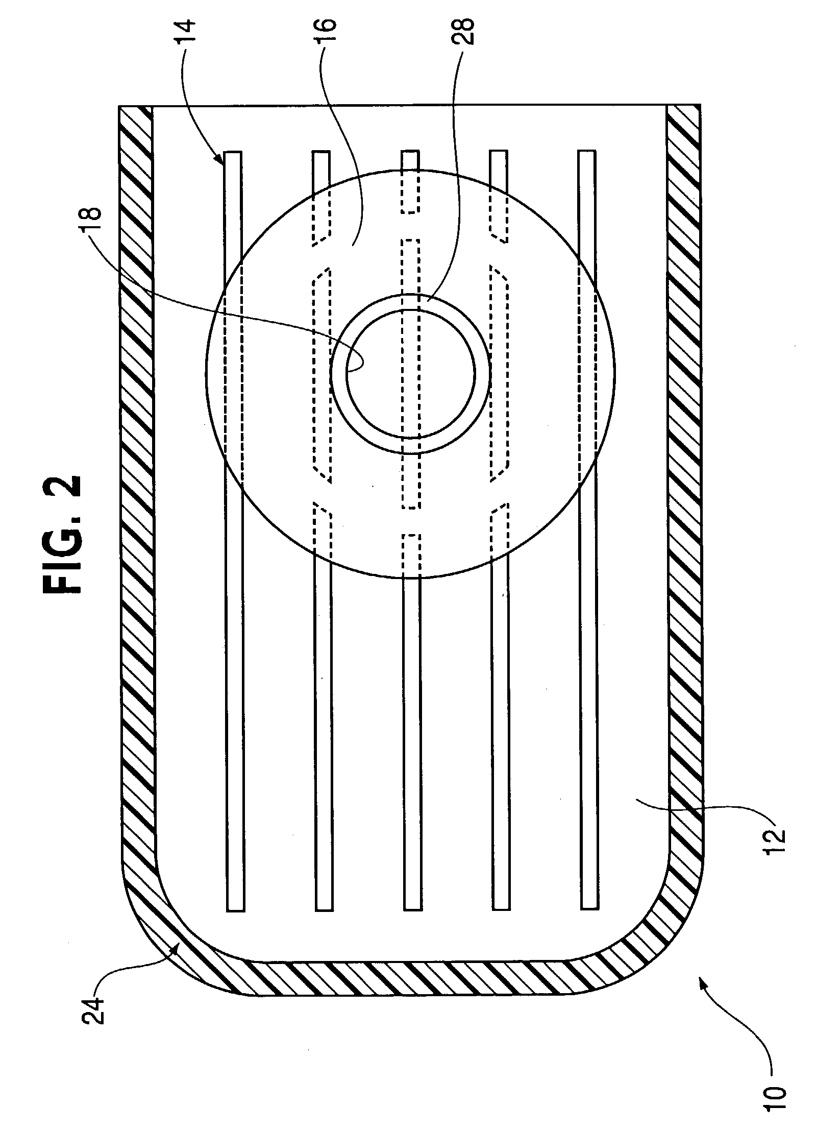
[0019]The invention will now be described with reference to the drawing figures, in which like reference numerals refer to like parts throughout. An embodiment in accordance with the present invention provides a suction-side transmission or engine filter comprising a filter bag having an inner support frame and filter bag outlet coincident with the outlet port of the transmission or engine filter.

[0020]The suction-side transmission or engine filters according to the present invention provide an outside-in flow scheme, i.e. dirty fluid enters the transmission or engine filter through the transmission or engine filter intake port and exists outside the filter bag. The dirty fluid is “purified” by passing through the filter media into the inside of the filter bag. The purified liquid then flows from the inside of the filter bag directly through the filter bag outlet, which is coincident with the transmission or engine filter outlet port, to the transmission pump in the case of a transm...


PUM


Abstract

A suction-side transmission or engine filter includes a filter bag assembly having an outlet portion and a media bag enclosing an inner support structure, the filter bag assembly is contained at least partially within a housing having an outlet port. The outlet portion and outlet port are aligned and sealed together creating an outside-in fluid flow scheme.

Description

FIELD OF THE INVENTION[0001]The present invention relates generally to engine and transmission filters. The present invention relates more specifically to suction-side engine or transmission filters having an outside-in flow scheme.BACKGROUND OF THE INVENTION[0002]Currently, suction-side transmission filters having a media-in-bag configuration employ the media in an inside to outside fluid flow scheme. Consequently, dirty fluid enters the bag from the transmission filter inlet and is cleaned as it exits the bag into two fluid regions (one above and one below the bag). The clean fluid then travels toward the transmission filter outlet. Typically, there is a region where the two clean flow regions join and then exit the transmission filter outlet.[0003]Media bags with inside-out flow schemes can be difficult to incorporate into some transmission filter designs, for example, transmission filters with inlets at an angle or inlets particularly close to the side-wall of the filter. Also, ...

Claims


Application Information

Patent Timeline
08 Aug 2006
Publication
US7087160B2
IPC
B01D35/027; B01D29/15; F01M11/03; B01D29/11; B01D29/13; B60K17/08; F16H57/02; F16H57/04
CPC
B01D35/0273; F16H57/0402; Y10S264/48; F01M11/03; B60K17/08
Inventors
BEER, MARKUS; WOLFORD, JAMES