Interlocking pin system

Inactive Publication Date: 2006-08-15
DUNNING SANDY L
View PDF6 Cites 16 Cited by
  • Summary
  • Abstract
  • Description
  • Claims
  • Application Information

AI Technical Summary

Benefits of technology

[0018]It is therefore an object of the present invention to provide a new and improved interlocking pin system which has all of the advantages of the prior art pin systems of known designs and configurations and none of the disadvantages.
[0019]It is another object of the present invention to provide a new and improved interlocking pin system which may be easily and efficiently manufactured and marketed.
[0020]It is further an object of the present invention to provid

Problems solved by technology

While these devices fulfill their respective, particular objectives and requirements, the aforementioned patents do not describe an interlocking pin s

Method used


Image

  • Interlocking pin system
  • Interlocking pin system
  • Interlocking pin system

Examples


Example

[0044]The same reference numerals refer to the same parts throughout the various Figures.

DESCRIPTION OF THE PREFERRED EMBODIMENT

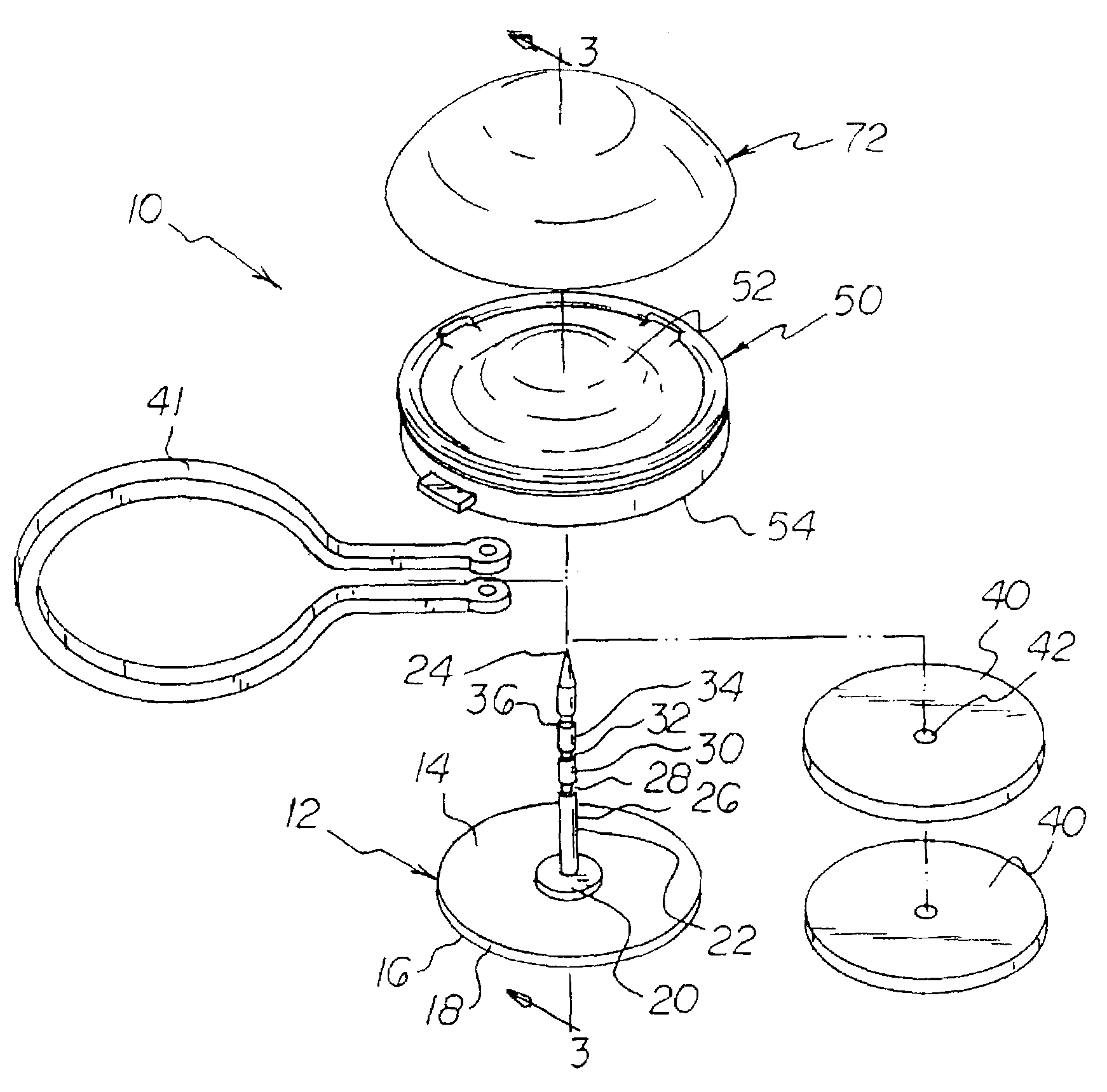
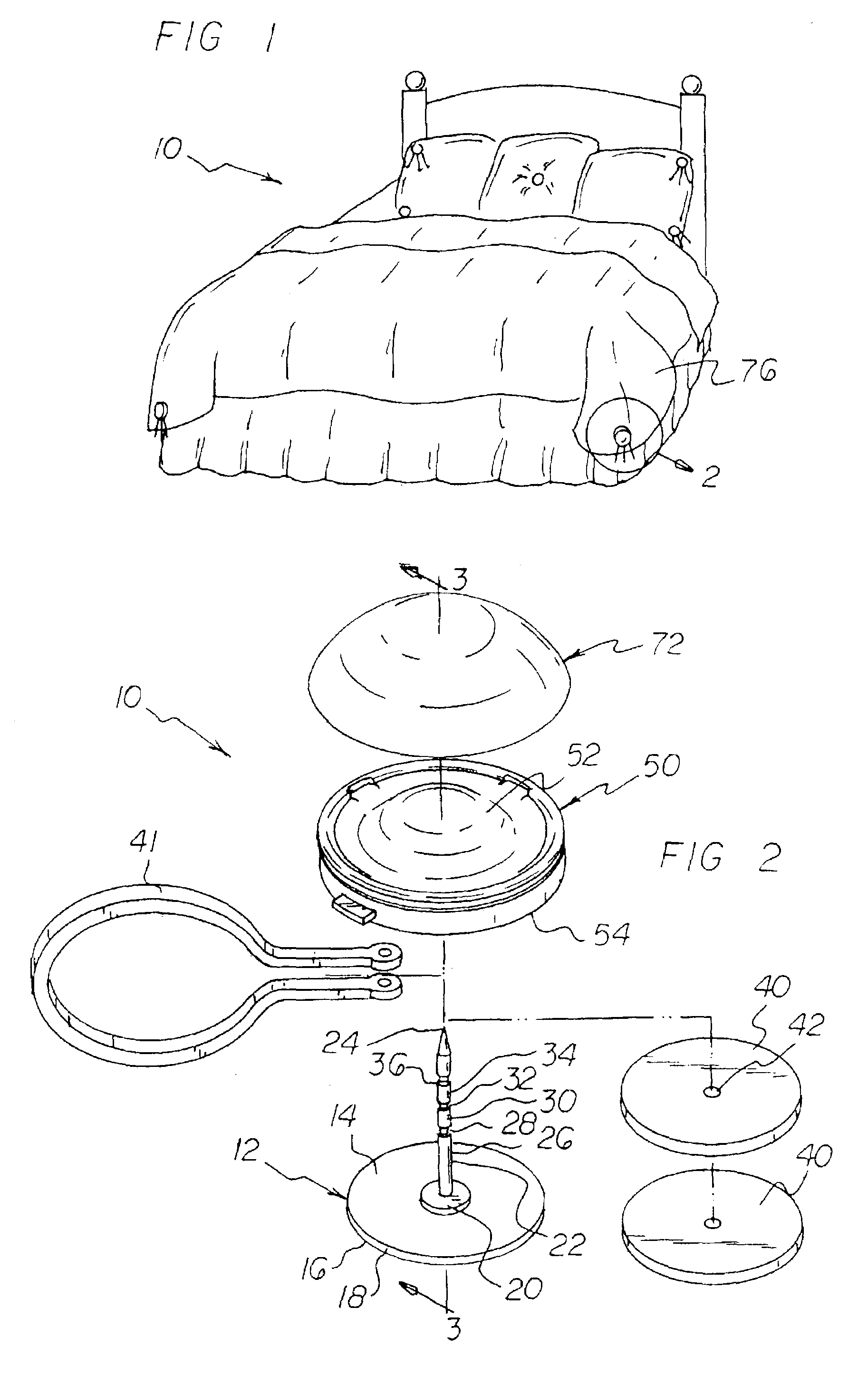
[0045]With reference now to the drawings, and in particular to FIG. 1 thereof, the preferred embodiment of the new and improved interlocking pin system embodying the principles and concepts of the present invention and generally designated by the reference numeral 10 will be described.

[0046]The present invention, the interlocking pin system 10 is comprised of a plurality of components. Such components in their broadest context include a base disk, a coupling housing, and a decorative convex member. Such components are individually configured and correlated with respect to each other so as to attain the desired objective.

[0047]First provided is a base disk 12. The base disk is of a first diameter. The base disk has a thin cylindrical configuration. The base disk also has a top face 14, a bottom face 16 and a periphery 18 there around. The top face has a conc...


PUM


Abstract

A base disk has a top face with a coaxial coupling pin with a pointed tip, spacer portions and notches. A coupling housing has a lower surface with an aperture. The housing has a releasable coupling mechanism. Male and females ends of the coupling mechanism are situated opposite each other and around the aperture. The male and female ends have biasing means and each has a pair of inward flanges with apertures and an outward tab. A supplemental member couples to the upper surface of the coupling housing.

Description

BACKGROUND OF THE INVENTION[0001]1. Field of the Invention[0002]The present invention relates to an interlocking pin system and more particularly pertains to decorating and securing duvet covers to down comforters, and also pertains to decorating and / or securing apparel, upholstery, and the like.[0003]2. Description of the Prior Art[0004]The use of pin systems of known designs and configurations is known in the prior art. More specifically, pin systems of known designs and configurations previously devised and utilized for the purpose of decorating and securing materials through known methods and apparatuses are known to consist basically of familiar, expected, and obvious structural configurations, notwithstanding the myriad of designs encompassed by the crowded prior art which has been developed for the fulfillment of countless objectives and requirements.[0005]By way of example, U.S. Pat. No. 3,534,446 to Silver discloses a fastener with ornamental front. U.S. Pat. No. 3,623,192 ...

Claims


Application Information

Patent Timeline
IPC IPC(8): A44B1/04A47C21/02A47H1/00A47H13/00
CPCA47C21/022A47H13/06A47H15/04Y10T24/23A47H2023/003Y10T24/4625A44D2201/36
Inventor DUNNING, SANDY L.
Owner DUNNING SANDY L
Why Eureka
Try Eureka