Coupling structure for a sliding track and a mounting bracket

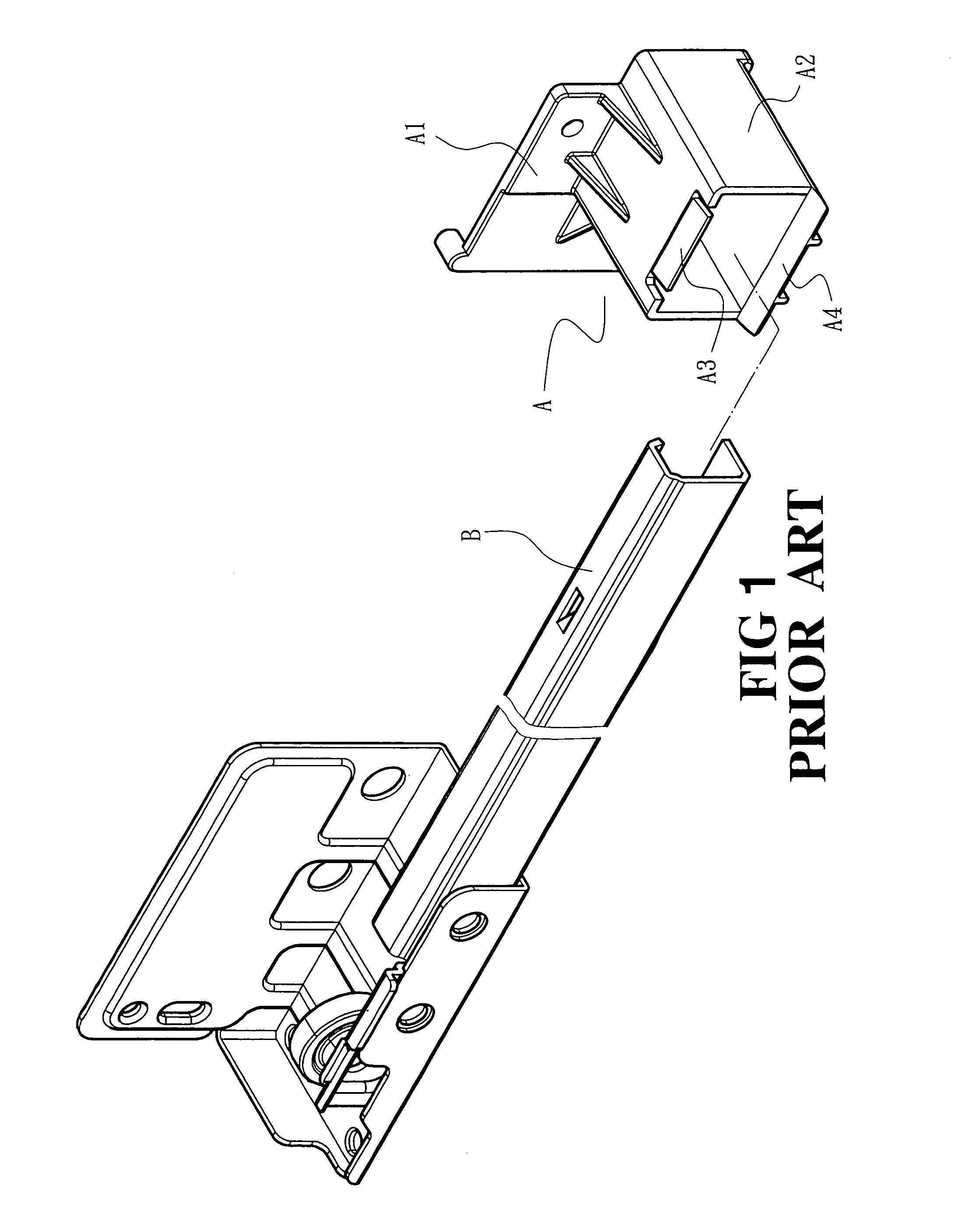
a technology of sliding track and mounting bracket, which is applied in the direction of drawers, furniture parts, domestic applications, etc., can solve the problems that the compression coupling between the tab ab>3/b> and the sliding track b cannot withstand great external forces

Active Publication Date: 2006-08-15
KING SLIDE WORKS CO LTD
View PDF14 Cites 26 Cited by
  • Summary
  • Abstract
  • Description
  • Claims
  • Application Information

AI Technical Summary

Benefits of technology

[0005]In view of the problems set forth above, the object of the invention is to provide a coupling structure for a sliding track and a mounting bracket so that the rear end of the sliding track may be coupled in the mounting bracket more securely without slipping away.

Problems solved by technology

However, the compressed coupling between the tab A3 and the sliding track B cannot withstand great external forces.

Method used


Image

  • Coupling structure for a sliding track and a mounting bracket
  • Coupling structure for a sliding track and a mounting bracket
  • Coupling structure for a sliding track and a mounting bracket

Examples


Embodiment Construction

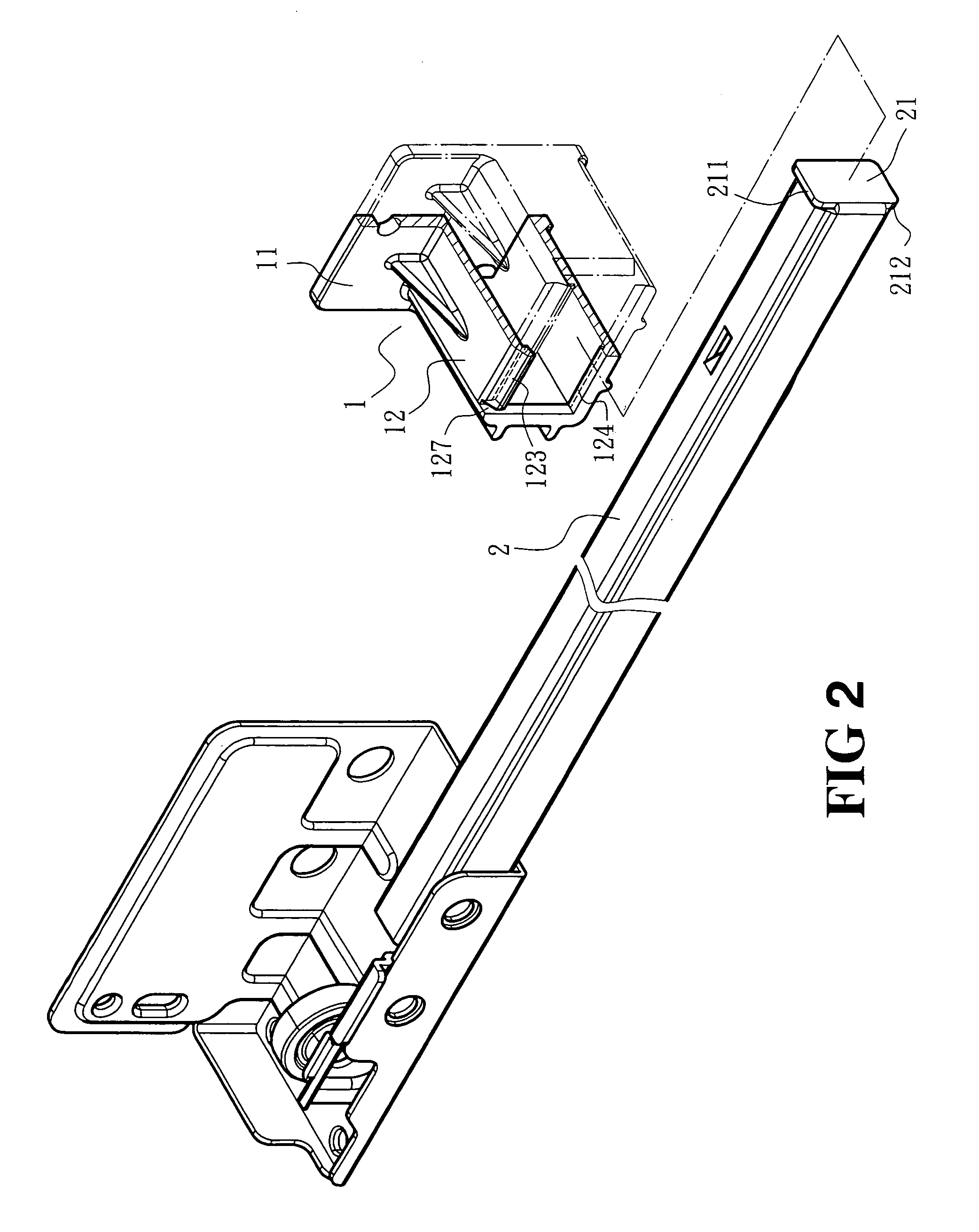
[0015]Referring to FIG. 2, the mounting bracket 1 employed in the present invention mainly includes a rear mounting plate 11 and a frame shell 12.

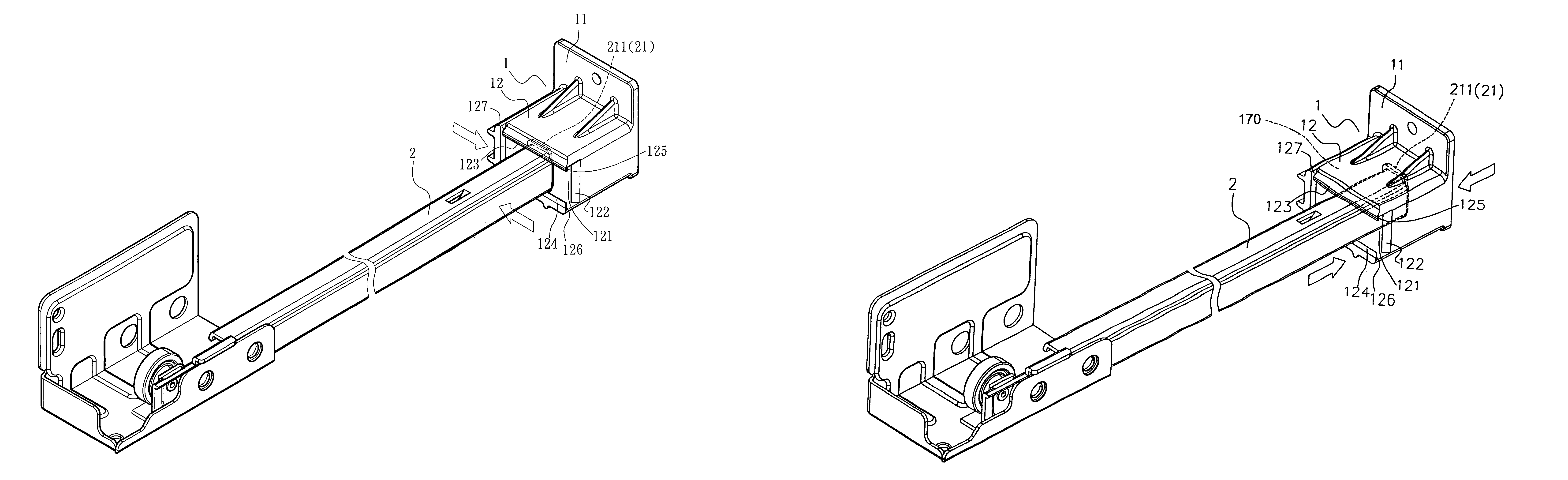
[0016]Referring to FIG. 3, the frame shell 12 has a front opening end. On one side of the front opening end there is a guiding notch 121. The sidewall of the frame shell 12 adjacent to the guiding notch 121 has a vertical edge at the front side forming a sloped guiding surface 122. The upper edge and the lower edge of the front opening end of the frame shell 12 have respectively an upper retaining flange 123 and a lower retaining flange 124. The upper retaining flange 123 and the lower retaining flange 124 have one end abutting the guiding notch 121, forming respectively an upper ramp 125 and a lower ramp 126. The upper retaining flange 123 has another end, forming a slit 127, also see FIG. 2, so that the upper retaining flange 123 is flexible to provide an elastic force to press a sliding track 2. The sloped guiding surface 122, the upper...


PUM


Abstract

A coupling structure for a sliding track and a mounting bracket includes a rear mounting plate and a frame shell. The frame shell has a front opening end which has one side forming a guiding notch. The front opening end further has an upper and a lower retaining flange on the upper edge and a lower edge, which form respectively a ramp at one end adjacent to the guiding notch. The upper retaining flange has a slit formed at another end so that the upper retaining flange becomes flexible and elastic to facilitate pressing of the sliding track. The sliding track has a retaining plate on the rear end to form an upper flange and a lower flange extending outside the sliding track. The flanges may slide transversely through the guiding notch to allow the sliding track to enter the frame shell and be moved longitudinally inwards for positioning.

Description

FIELD OF THE INVENTION[0001]The present invention relates to a coupling structure for a sliding track and a mounting bracket and particularly to a novel design to achieve a secured coupling between a mounting bracket and the rear end of a sliding track without separation.BACKGROUND OF THE INVENTION[0002]Conventional drawer sliding tracks generally include a mounting bracket to facilitate user DIY assembly and fast installation. References can be found in U.S. Pat. Nos. 5,257,861, 5,387,033, 5,636,820, 5,746,490, and 5,823,648. Some of them include a mounting bracket with an integrated flange or stop member to retain the rear end of the sliding track so that the sliding track may be moved within a limited range without slipping away when subjected to external forces. Some others have bent plates fastened to the mounting bracket to achieve the same result.[0003]Another example is a mounting bracket A made from plastics as shown in FIG. 1 (also referring to U.S. Pat. No. 6,302,502). Th...

Claims


Application Information

Patent Timeline
Patent Type & Authority Patents(United States)
IPC IPC(8): A47B88/04A47B88/00
CPCA47B88/044A47B88/43
Inventor CHEN, KEN-CHINGHUANG, TING-TSAI
Owner KING SLIDE WORKS CO LTD
Why Eureka
Try Eureka