Omni-direction rotatable dual-cup suction device

a dual-cup, omni-direction technology, applied in the direction of machine supports, manufacturing tools, other domestic articles, etc., to achieve the effect of improving the usefulness and value of a tablet computer, enhancing practicability, and multiple efficacy

Active Publication Date: 2012-02-23
LIH YANN INDAL
View PDF23 Cites 26 Cited by
  • Summary
  • Abstract
  • Description
  • Claims
  • Application Information

AI Technical Summary

Benefits of technology

[0010]To solve such problems and drawbacks, the present invention provides an omni-direction rotatable dual-cup suction device, which comprises two suction cups, which are respectively combined with and in communication with two evacuation structures, so that the two evacuation structures can evacuate air from the suction cups to induce vacuum suction forces. The two suction cups are respectively provided with a mounting seat and an attaching seat for securely coupling the two evacuation structures to the two suction cups. The mounting seat comprises a pillar fixed thereto. A collar receives a ball end of a bar therein and is attached to the pillar by a threaded tightening element. The ball-ended bar is coupled to a threaded rod, which extends through an internally-threaded locking knob and received into the attaching seat to be secured by a nut. With such an arrangement, one of the suction cups can be attached to a planar fixture surface, while the other suction cup can be used to hold an article, such as a tablet computer. The tightening element can be operated to release the pillar so that the orientation of the article and the one of the suction cups carrying the article can be adjusted to thereby enhance the practicability for exhibition purposes and realize multiple efficacies.
[0011]As compared to the known devices, the effectiveness of the present invention is that the omni-direction rotatable dual-cup suction device can be attached to for example a desk top with one suction cup while holding a tablet computer with another suction cup in a manner allowing for adjustment of orientation of the tablet computer to for example face a user. This allows the tablet computer to be oriented to an optimum angular position for use of the computer, so that the usefulness and value of a tablet computer can be improved, and allowing the tablet computer to be used for exhibition purposes by attaching the suction device to a wall and orienting the computer toward people. In this way, the effect of exhibition can be significantly improved for attracting consumers. Further, the suction device of the present invention can be attached inside a windshield of a car and allows a tablet computer attached thereto to be adjusted to the best orientation for watching by passengers sitting inside the car. As such, the usefulness of the tablet computer can be improved.

Problems solved by technology

The problem to be addressed by the present invention is that the existing suction devices, including the simple suction cup, the depression type suction device, and the pumping type suction device, all show drawbacks, wherein the simple suction cup provides a suction force that is very limited and insufficient to support a tablet computer, which is retained on the suction cup by a clamp or a rack that provides a clamping force that may also be insufficient for a tablet computer; the depression type suction device provides a suction force that is slightly enlarged, but is still insufficient and of a limited level, due to the limited stroke of depression, and comprises no alarm mark, making it possible for an article to unexpectedly fall off the suction device due to leakage of air and thus loss of suction force thereby leading to damage of the article and any stuffs located around the suction device; and the pumping type suction device, although allowing repeated operation for air evacuation to provide a large suction force and comprising an alarm mark to easy identification of any possible dangerous situations, is not provided with orientation adjusting structure and lacks of a suitable structure for holding an article thereon.

Method used


Image

  • Omni-direction rotatable dual-cup suction device
  • Omni-direction rotatable dual-cup suction device
  • Omni-direction rotatable dual-cup suction device

Examples


Embodiment Construction

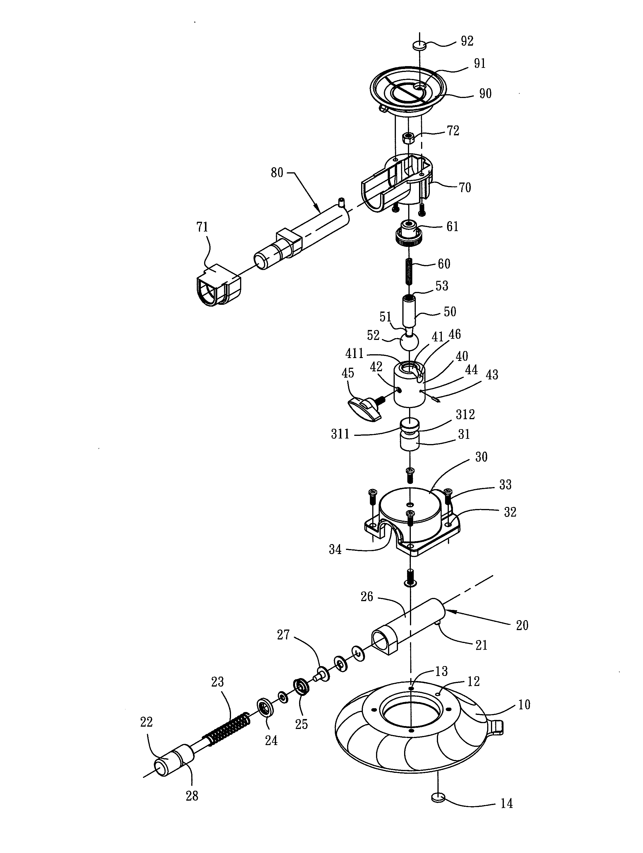
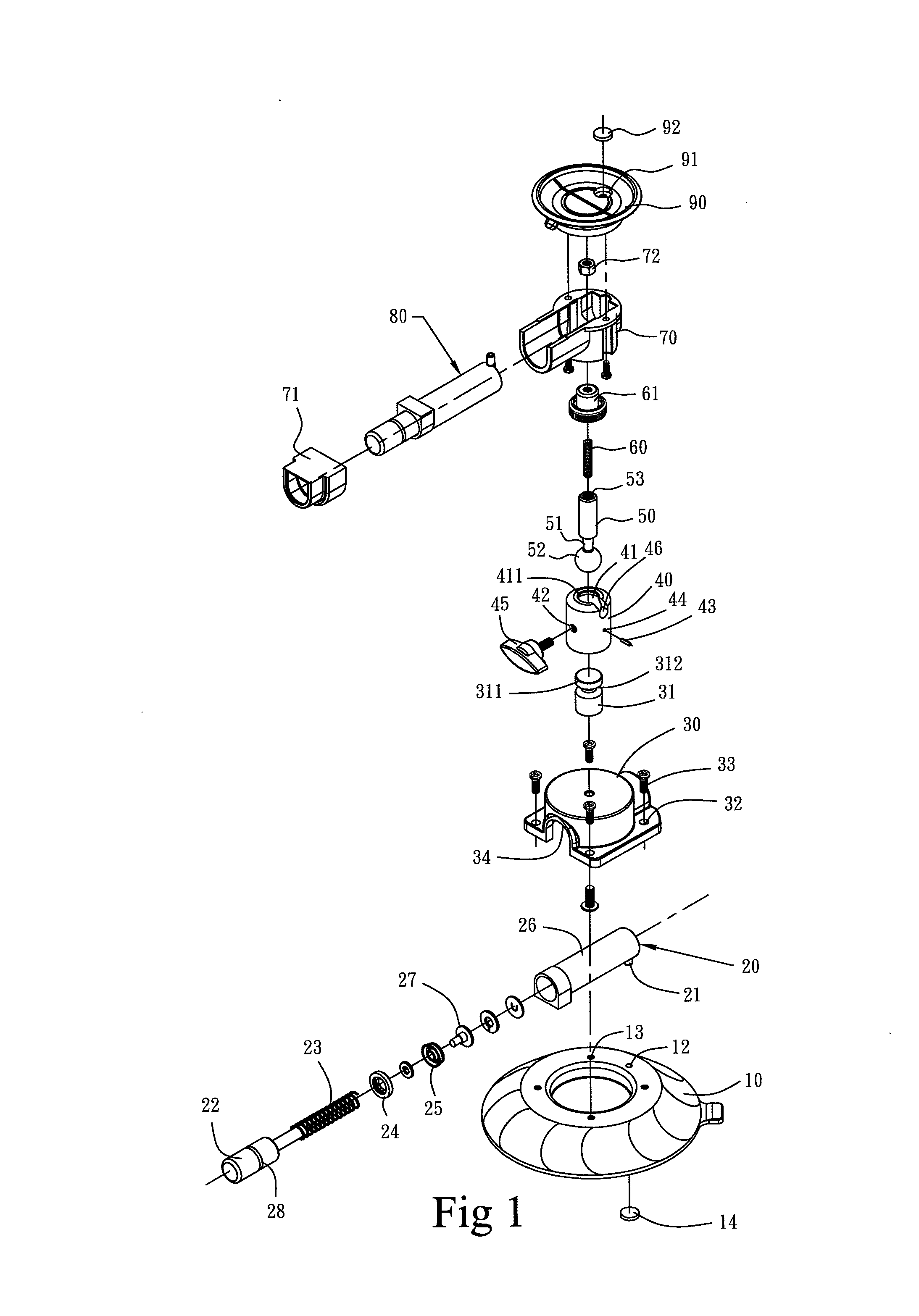
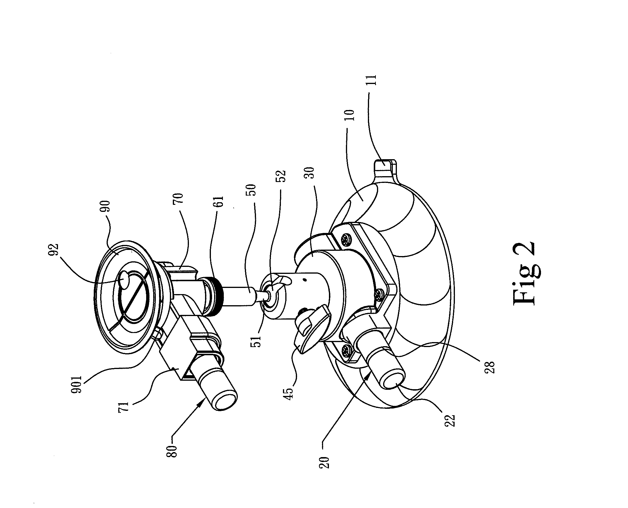
[0020]With reference to the drawings and in particular to FIGS. 1 and 2, which respectively show an exploded view and a perspective view of an omni-direction rotatable dual-cup suction device, the omni-direction rotatable dual-cup suction device of the present invention comprises first and second suction cups 10, 90, which are coupled to each through an orientation-adjustable coupling structure so that the relative angular position between the two suction cups 10, 90 is adjustable as desired.

[0021]The first suction cup 10 comprises a cup-like body having an open end that is positioned to face a given first direction, such as facing downward. The second suction cup 90 comprises a cup-like body having an open end that is orientated to face a given second direction, such as facing upward, which is generally not identical to the first direction. The first and second suction cups 10, 90 are respectively provided with first and second evacuation structures 20, 80, which are operable for s...


PUM


Abstract

An omni-direction rotatable dual-cup suction device includes two suction cups, which are respectively combined with and in communication with two evacuation structures, so that the two evacuation structures can evacuate air from the suction cups to induce vacuum suction forces. The two suction cups are respectively provided with a mounting seat and an attaching seat for securely coupling the two evacuation structures. The mounting seat includes a pillar fixed thereto. A collar receives a ball end of a bar therein and is attached to the pillar. The ball-ended bar is coupled to a threaded rod, which extends through an internally-threaded locking knob and received into the attaching seat to be secured by a nut. With such an arrangement, one of the suction cups can be attached to a planar fixture surface, while the other suction cup can be used to hold an article and is orientation adjustable in any direction.

Description

BACKGROUND OF THE INVENTION[0001]1. Field of the Invention[0002]The present invention relates to the field of orientation-adjustable suction device, and in particular to an omni-direction rotatable dual-cup suction device, of which one suction cup can be attached to a planar fixture surface and another suction cup can be used to hold for example a tablet computer to allow for easy orientation adjustment to facilitate the operation of the computer by adjusting orientation or the use of the computer in an exhibition.[0003]2. The Related Arts[0004]Suction devices are commonly used. Various constructions of suction device are known, including a simply-structured suction cup that is often used to hold a navigation device or a smart mobile phone, such as PDA, inside an automobile by having a rack or clamp receiving and holding the navigation device and a cup body attached inside the front windshield. Such a simply-structured suction cup often provides a suction force that, although capabl...

Claims


Application Information

Patent Timeline
Patent Type & Authority Applications(United States)
IPC IPC(8): F16B47/00
CPCF16B47/00F16M11/041F16M2200/022F16M13/00F16M13/022F16M11/14
Inventor LIAO, PO LIN
Owner LIH YANN INDAL
Why Eureka
Try Eureka