
3-D imaging arrangements

a three-dimensional imaging and arrangement technology, applied in the field of three-dimensional imaging arrangement, can solve the problems of difficult to achieve the desired consistency among stimuli (or cues), physical and mental discomfort of presentations, and difficulty in maintaining the desired consistency of stimuli, so as to reduce disparities, stimulate binocular depth perception, and achieve the effect of reducing disparities

Inactive Publication Date: 2006-08-15
SIEGEL MEL +1
View PDF4 Cites 18 Cited by
  • Summary
  • Abstract
  • Description
  • Claims
  • Application Information

AI Technical Summary

Benefits of technology

[0013]The selection of center-of-interest can preferably be accomplished by sliding the left-right perspective images over each other until they coincide at the center-of-interest. The images can then be suitably cropped so that the two fields-of-view coincide at the distance of the center-of-interest. Alternatively, the camera sensors (CCD's) could be shifted at the time of image capture. This would avoid the need to crop, such that picture area would not be lost, nor would the desirable constancy of aspect ratio be compromised.
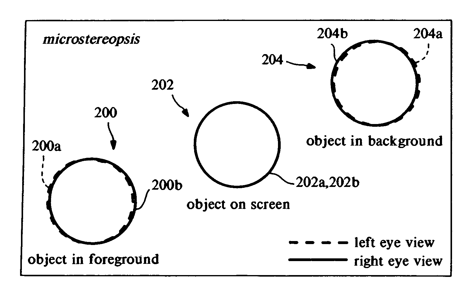
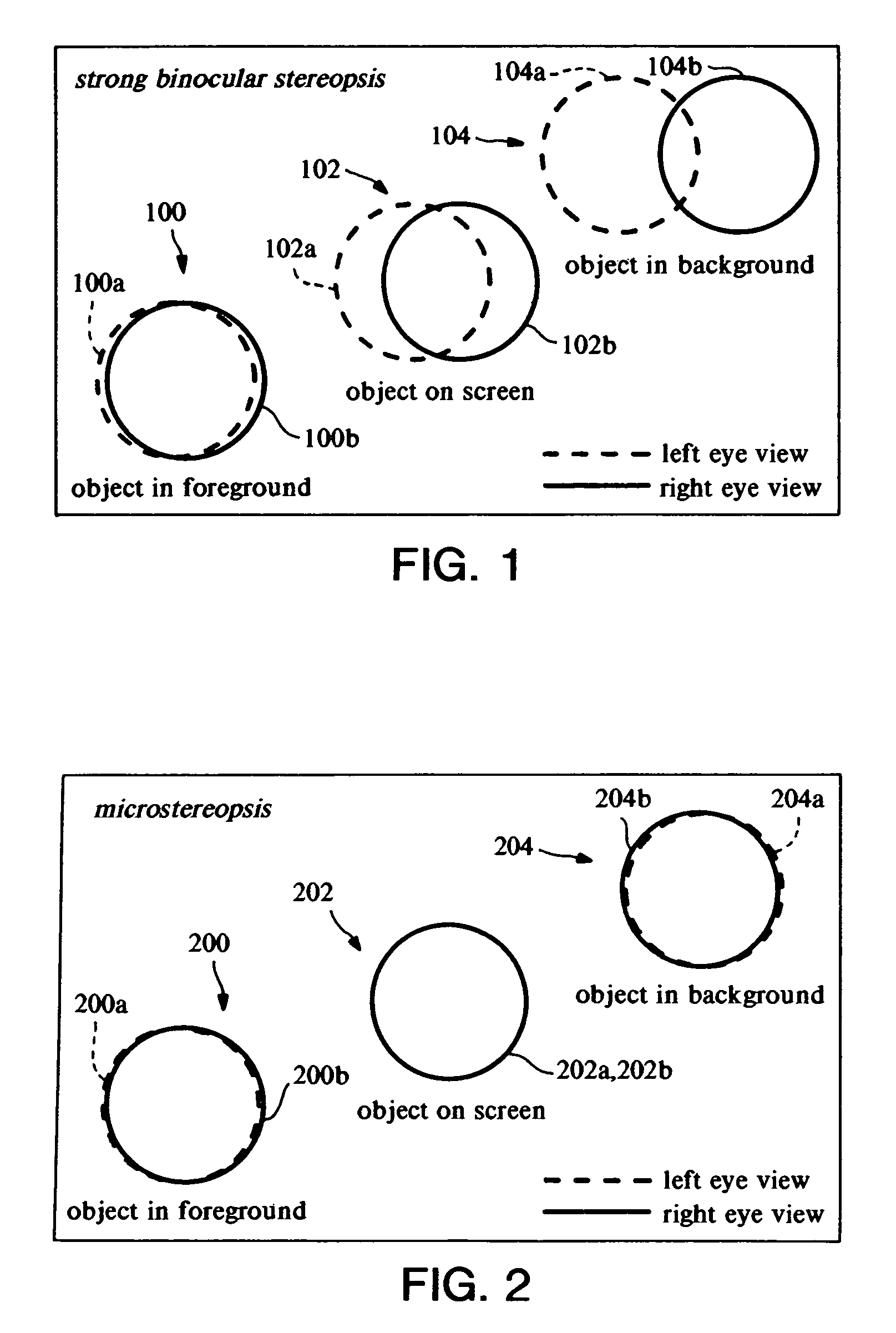
[0015]It has been found that the combination of center-of-interest correction and microstereopsis greatly minimizes the convergence-accommodation conflict. When consistently combined with other depth cues, this combination effectively achieves the desirable consequence, encountered in accordance with at least one embodiment of the present invention, that the viewer sees the scene in depth without experiencing the undesirable side effects (e.g., “virtual reality sickness”) that are normally regarded as a necessary accompaniment of 3D-stereoscopic displays.
[0016]In accordance with at least one presently preferred embodiment of the present invention, it is also recognized that the combination of center-of-interest correction and microstereopsis has the desirable side effect of enabling an entirely new class of stereoscopic display hardware paradigms, in view of a surprisingly effective utilization of “crosstalk” in accordance with at least one presently preferred embodiment of the present invention.

Problems solved by technology

Particularly, conventional stereo displays often involve various types of physical and mental discomfort, to varying degrees.
Technical inconveniences have also been noted among known devices, such as specialized types of eyewear that must be worn and “viewing zones” that are often perceived to be bothersome.
At a basic level of the musculature of the human visual system, there is a well-known conflict, known as convergence-accommodation (sometimes termed “vergence-accommodation”, among other things) that makes it difficult to achieve the desired consistency among stimuli (or cues).
The conflict between what the convergence muscles and the focusing muscles are each communicating to the brain about the scene's depth is thus a major disturbing conflict.

Method used


Image

  • 3-D imaging arrangements
  • 3-D imaging arrangements
  • 3-D imaging arrangements

Examples


Embodiment Construction

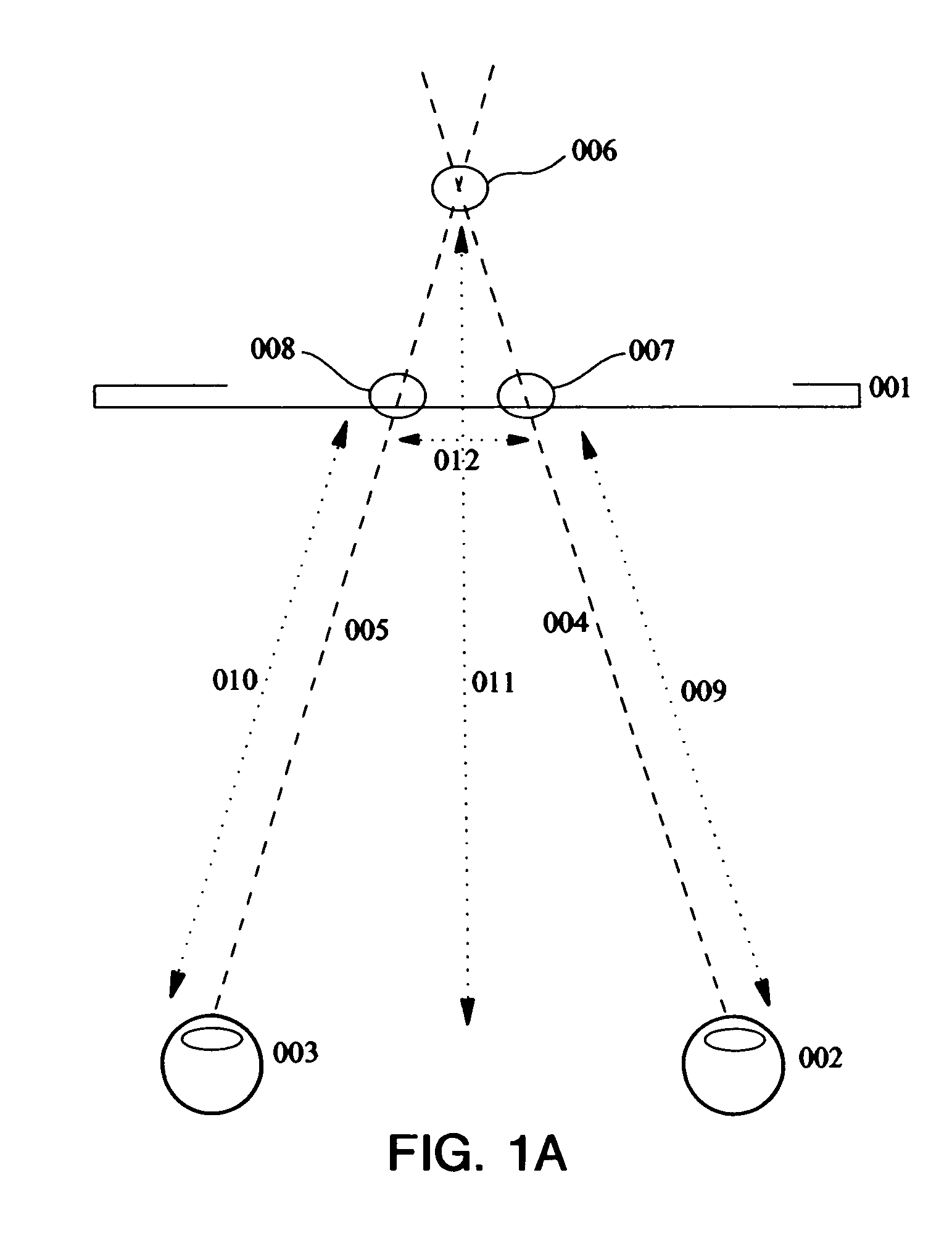
[0023]Three-dimensional imagery can be displayed a flat screen 001 with the arrangement illustrated in FIG. 1a. As shown, right eye 002 and left eye 003, respectively, perceive screen points 007 and 008 along respective lines of sight 009 and 010. Shutter, barrier, or other means not illustrated explicitly in FIG. 0 are employed to prevent right eye 002 from perceiving screen point 007 intended for left eye 003, and to prevent left eye 003 from perceiving screen point 008 intended for right eye 002. Lines of sight 009 from right eye 002 and 010 from left eye 003 converge at virtual scene point 006 behind screen 001. The human brain fuses separate right eye 002 and left eye 003 perceptions of screen points 007 and 008 into a single three-dimensional perception at virtual scene point 006. The distance 012 between corresponding screen points 007 and 008 is called the “disparity”.

[0024]Conventional 3D displays use large on screen disparities, as illustrated in FIG. 1. As shown, the left...


PUM


Abstract

A viewing system and method for producing at least one image for being perceived as three-dimensional, including at least one of: a provision for compensating the center-of-interest of the at least one image in such a manner as to reduce convergence-accommodation conflict; a provision for configuring the viewing system such that crosstalk produced by a stereo display is perceived as foreground and background blur instead of ghosting; and a provision for viewing the at least one image via automicrostereopsis.

Description

CROSS-REFERENCE TO RELATED U.S. APPLICATIONS[0001]This application claims priority from U.S. Provisional Patent Application Ser. No. 60 / 116,691, filed on Jan. 21, 1999.FIELD OF THE INVENTION[0002]The present invention generally relates to arrangements for three-dimensional imaging.BACKGROUND OF THE INVENTION[0003]Generally, a need has been recognized for what may be termed “kinder gentler stereo”.[0004]In this context, “stereo” refers to a system for putting information on a two-dimensional, essentially flat screen surface (such as front and back projection “movie” screens, CRTs, LCDs, etc.) in a way that causes the observer to see an image in depth corresponding to the depth in the original scene. The scene could be a real scene captured by an appropriate camera system, a virtual scene generated by a computer, or a hybrid of these.[0005]The term “kinder gentler” is provided as a contrast to what has been experienced with known conventional devices. Particularly, conventional stereo...

Claims


Application Information

Patent Timeline
Patent Type & Authority Patents(United States)
IPC IPC(8): H04N13/00H04N1/04H04N13/02H04N15/00H04N13/125
CPCH04N13/0011H04N13/0018H04N13/111H04N13/122H04N13/125
Inventor SIEGEL, MELTOBINAGA, YOSHIKAZU
Owner SIEGEL MEL
Learn More