Lawn mower having adjustable flow control baffle

a technology of flow control and lawn mower, which is applied in the field of lawn mowers to achieve the effect of quick and easy access by users

Inactive Publication Date: 2006-08-22
TORO CO THE
View PDF13 Cites 38 Cited by
  • Summary
  • Abstract
  • Description
  • Claims
  • Application Information

AI Technical Summary

Benefits of technology

This patent describes a special kind of garden mower called a multi-blade lawnmower. It has cutters on its sides for collecting grass clipping and can switch between being a regular mower (called a side discharge) or a mulcher (which throws out the clipping). There are controls inside the machine that help move the air and clipping around. The new feature added is a movable bar that helps guide the clipping towards the openings on the sides. Another improvement is a quick and easy way to change how well the machine guides the clipping - this makes it easier to use different types of machines depending on what needs doing.

Problems solved by technology

The technical problem addressed in this patent is how to convert between different types of commercial lawn mowers without requiring extensive work and downtime for installations.

Method used


Image

  • Lawn mower having adjustable flow control baffle
  • Lawn mower having adjustable flow control baffle
  • Lawn mower having adjustable flow control baffle

Examples


Embodiment Construction

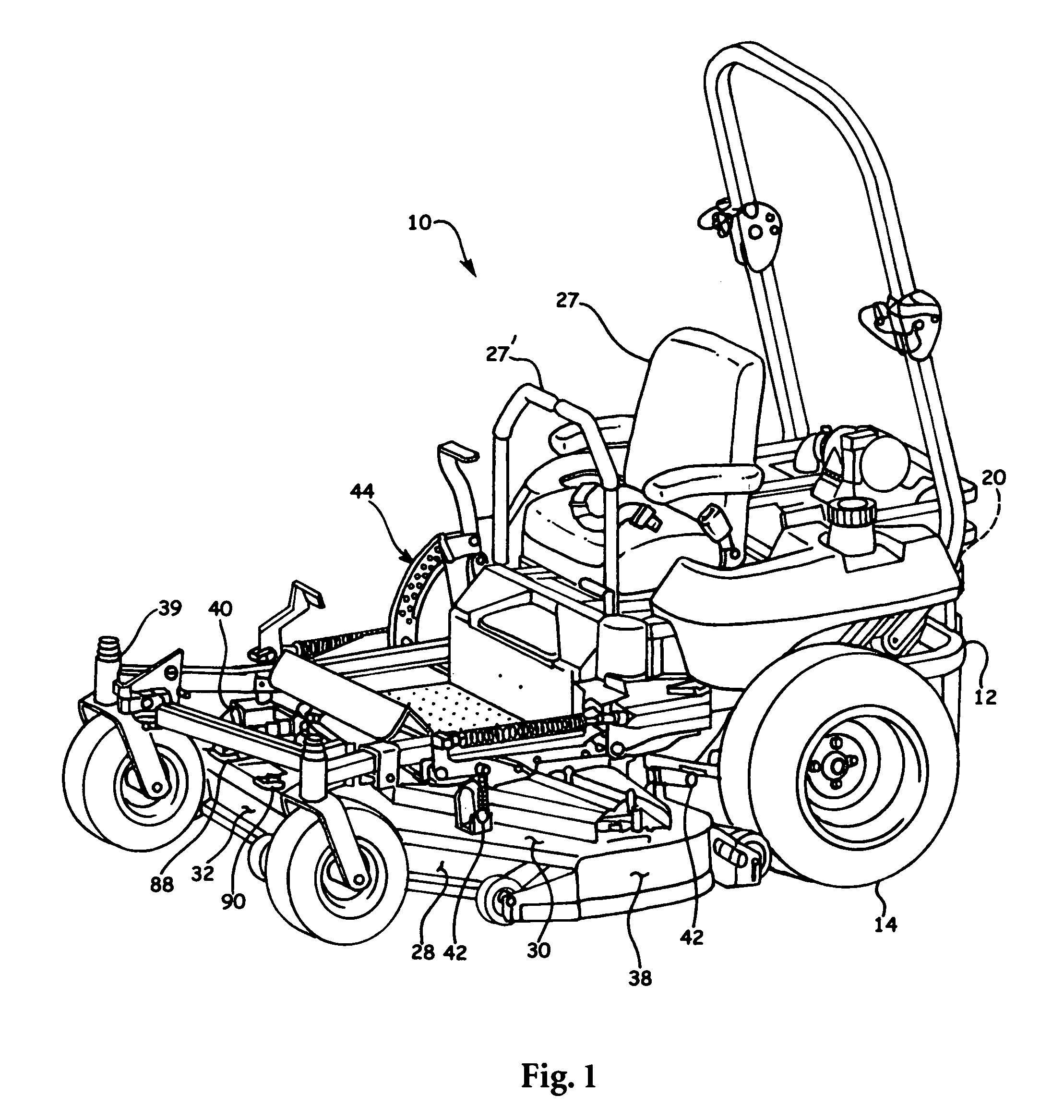
[0015]Referring to FIG. 1, the numeral 10 refers to a multiblade lawn mower upon which the invention herein is utilized. Although the invention described herein is ideally suited for use with a riding mower, it is believed that the invention described herein also has applicability with respect to walk-behind mowers. Mower 10 includes a frame 12 having a pair of drive wheels 14 positioned on opposite sides of the frame means 12 at the rearward end of the mower. An internal combustion engine 20 is mounted frame 12. Engine 20 is operatively connected to a pair of hydraulic pumps which are operatively connected to hydraulic motors operatively connected to the drive wheels 14, respectively. Mower 10 also includes an operator's station 27 and steering controls 27′.

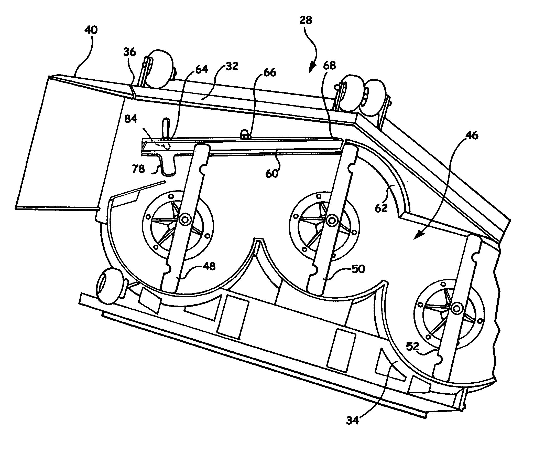
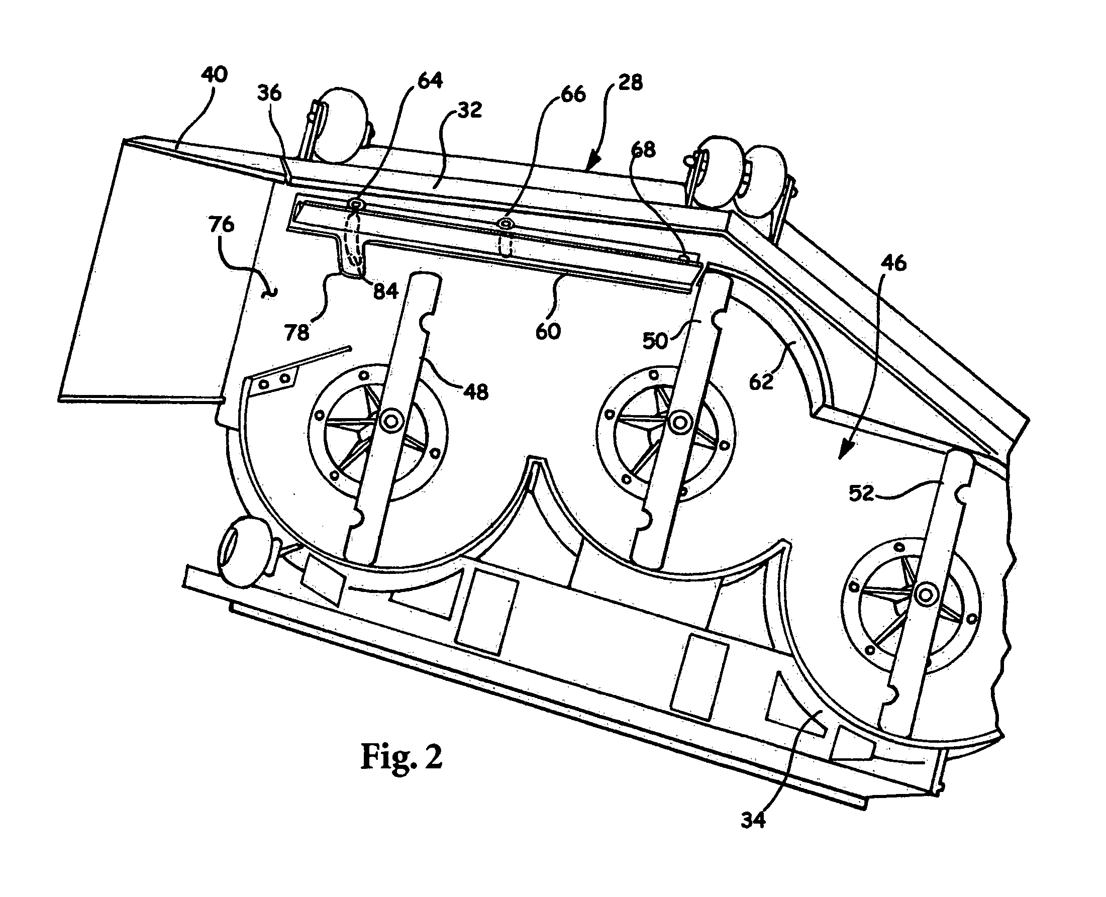
[0016]Mower 10 includes a mower deck 28 at the forward end thereof which includes a top wall 30, front wall 32, rear wall 34 (not shown in FIG. 1), and opposite side walls 36 and 38. Caster wheel assemblies 39 support the forwar...


PUM


Abstract

A mower deck having a plurality of cutting blades carried within a cutting chamber and having a plurality of flow control baffles positioned within the cutting chamber including a first flow control baffle being movably connected to the mower deck. The first flow control baffle being selectively movable between a pair of orientations within the cutting chamber during a mowing operation. In a preferred embodiment, the first flow control baffle may be positioned between the pair of orientations without access to the cutting chamber.

Description


Claims


Application Information

Patent Timeline
Owner TORO CO THE
Why Eureka
Try Eureka