Chair

a chair and seat technology, applied in the field of chairs, can solve the problems of shirt-pushing effect, inability to achieve satisfactorily, and inability to achieve continuous seat surface,

Inactive Publication Date: 2004-02-24
HAWORTH BUROEINRICHTUNGEN
View PDF5 Cites 66 Cited by
  • Summary
  • Abstract
  • Description
  • Claims
  • Application Information

AI Technical Summary

Problems solved by technology

Larger backward tilts, in particular of the backrest, are desired at many work stations, for example air traffic control centers or PC work stations, but cannot be satisfactorily achieved by present synchronization mechanisms, because sequence errors occur at larger opening angles, for example relative movements between the back and the backrest that are too large, so that a shirt-pushing effect occurs.
A wrong synchronization ratio between the backrest and the seat is present, increasing a distance of the lower backrest area from the pelvis, so that an ergonomically disadvantageous gap occurs because of the pelvis rolling back, and sinking the lower backrest edge during backward tilt, so that a continuous seat surface is not achieved.

Method used


Image

  • Chair
  • Chair
  • Chair

Examples


Embodiment Construction

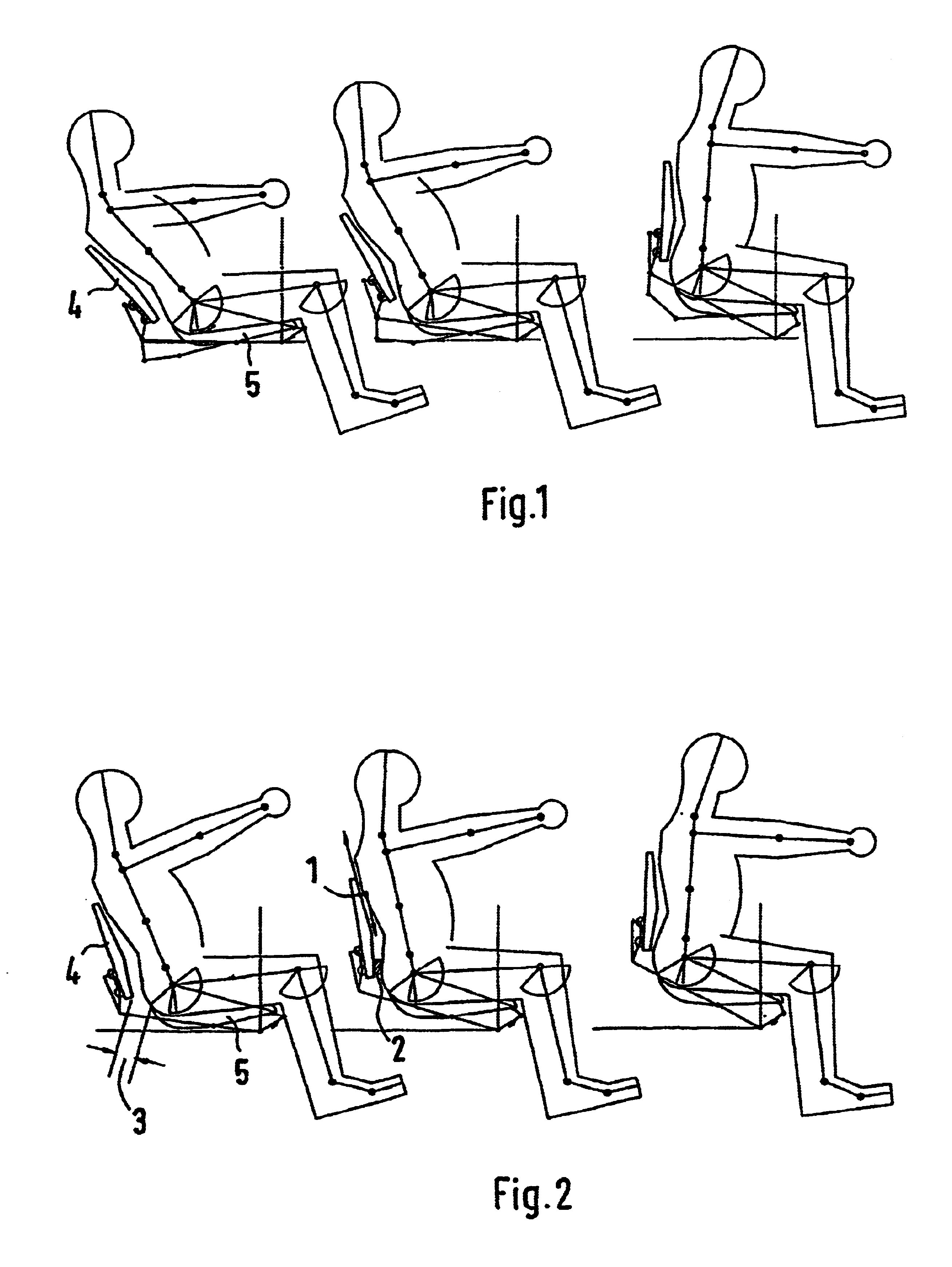
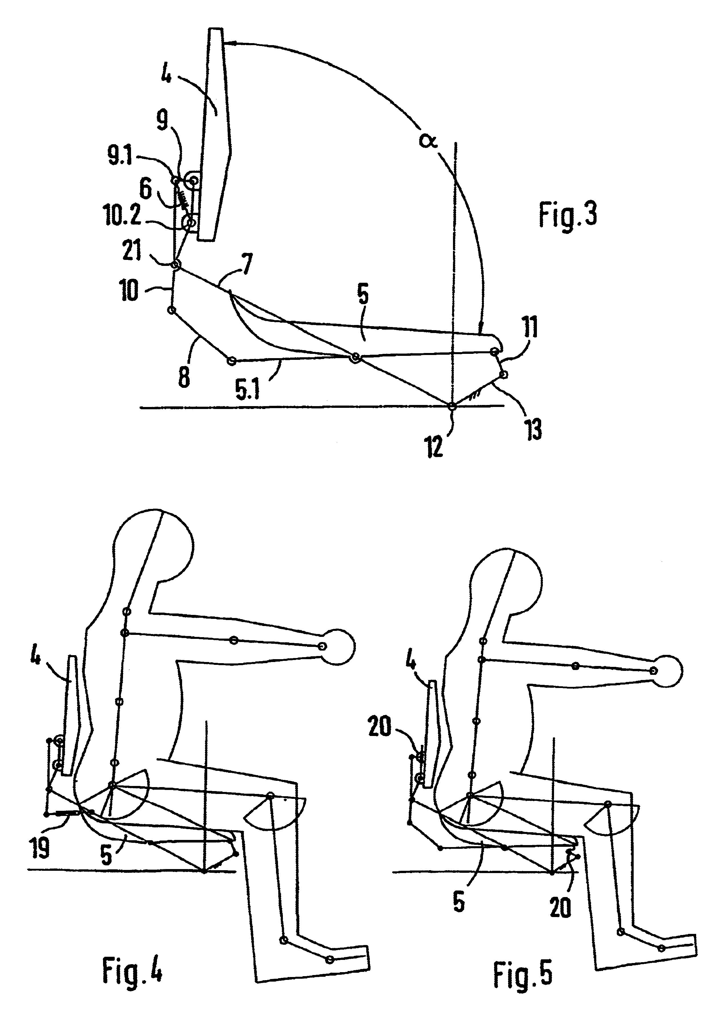
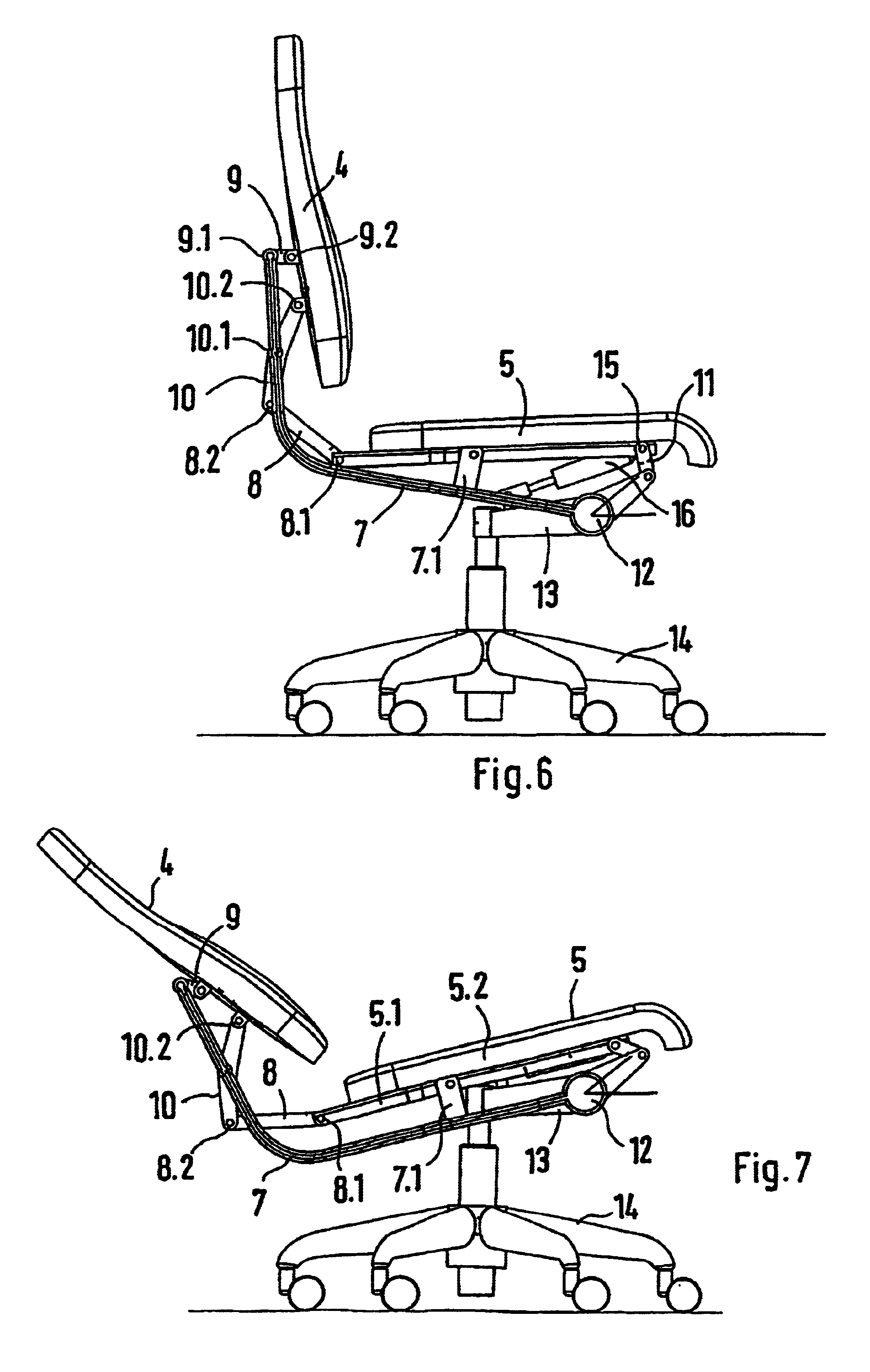
Three different seat and backrest tilts in connection with an expanded synchronization mechanism are shown in FIG. 1, in three position representations. The backrest 4 can be tilted relative to the seat 5 over a substantially greater opening range than with a conventional synchronization mechanism, such as shown in FIG. 2 for comparison. The expanded synchronization mechanism is schematically explained in FIG. 3 and shown in various representations by an exemplary embodiment in FIGS. 6 to 9.

The expanded synchronization mechanism has a number of articulated points, in which different lever elements are connected with each other. The movement of the backrest 4 and the seat 5 takes place around body-related virtual pivot points, so that the spine is supported in an ergonomically advantageous manner during seating. A seat rocker 11, oriented obliquely upward and toward the back, is hingedly connected by an upper section with a pivot shaft 15 on the seat, and by a lower section it is hin...


PUM


Abstract

A chair, in particular a work or office chair, having a seat mounted onto a chair frame. The front region of the seat can be inclined about a horizontal, pivoting shaft which is displaced upwards and downwards, following a spatial guide curve in relation to the chair frame. The seat is also connected in an articulated manner to a rocker which is directed upwards and extends backwards from an articulated rocker bearing fixed to the chair frame and which is connected at a distance from the rear edge of the seat, or at the side of said seat. The chair also includes a backrest which is attached to the section of the rocker that is directed upwards, the inclination of the backrest being disproportionately altered, in a forced manner, with the alteration of the inclination of the seat. This invention achieves an increased apex angle between the backrest and the seat, together with a uniform displacement because the backrest is coupled to the rocker by a coupling point and the seat is also coupled to the backrest by a control lever assembly, which is used to incline the backrest backwards in relation to the rocker, when the seat is inclined.

Description

1. Field of the InventionThis invention relates to a chair, in particular a work or office chair, having a seat, which is placed on a chair frame and can be tilted in a front area around a horizontal pivot shaft, which can be moved up and down on a spatial guide curve in relation to the chair frame, and which is hingedly connected to a rocker extending toward the rear from an articulated rocker bearing fixed on the chair frame and is thereafter spaced apart from the seat rear edge, or is laterally guided upward next to the seat. The chair also has a backrest coupled to the upward guided section of the rocker, with a tilt that is forcibly changed superproportionally when the tilting of the seat is changed.2. Discussion of Related ArtAn office chair is known from German Patent Reference DE 39 16 474 C2. With this known chair, the front end section of a rocker-like pivot lever extending under the seat is tiltably fastened on a bearing bracket of the chair frame, while a section, which ...

Claims


Application Information

Patent Timeline
Patent Type & Authority Patents(United States)
IPC IPC(8): A47C1/031A47C1/032
CPCA47C1/03255A47C1/03261A47C1/03279
Inventor BRUSKE, JOACHIM
Owner HAWORTH BUROEINRICHTUNGEN
Why Eureka
Try Eureka