Sheet switch, sheet switch module and panel switch

a switch module and switch technology, applied in the direction of contact surface shape/structure, emergency actuators, contact surfaces, etc., can solve the problems of difficult to achieve a thinned key switch, and increasing the thickness of the key switch, etc., to achieve a simple structure and high brightness

Inactive Publication Date: 2007-02-22
CITIZEN ELECTRONICS CO LTD
View PDF7 Cites 66 Cited by
  • Summary
  • Abstract
  • Description
  • Claims
  • Application Information

AI Technical Summary

Benefits of technology

[0019] An object of the present invention is to provide a sheet switch of simple structure thinned as much as possible, a sheet switch module provided with an illumination function allowing light to be guided efficiently in the sheet switch, and a flat-type panel switch which, by installation of the sheet switch module therein, is capable of being thinned and exhibits high brightness.

Problems solved by technology

However, because each of the above-mentioned conventional key switches has the structure in which each of the key tops 17 which controls each of the springs is illuminated by the corresponding light guiding plate 15, there is a problem that the key top 17 and the light guiding plate 15 must be provided separately from the spring 14, and this results in a key switch 11 having an increased thickness.
Increasing the overall thickness of the light guiding plate results in increased thickness of the key switch, thus making it difficult to achieve a thinned key switch.
Consequently, there is a problem that the key tops 17 have low brightness and that variations in brightness are marked.
If there is a gap in the circumference of the light guiding plate 15, light leaks trough the gap, leading to a problem of insufficient light illuminating each key top and insufficient brightness of the key tops.
Therefore, in the above-mentioned conventional key switches 1 and 11, it is not possible to obtain a thinned and effective key switch which illuminates the key tops 17 exclusively.

Method used


Image

  • Sheet switch, sheet switch module and panel switch
  • Sheet switch, sheet switch module and panel switch
  • Sheet switch, sheet switch module and panel switch

Examples


first embodiment

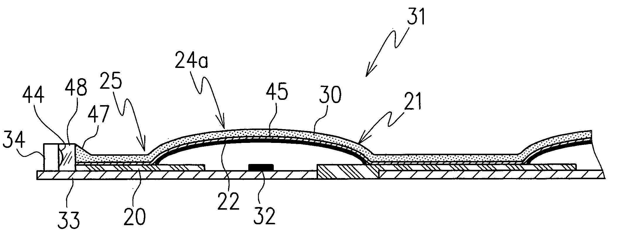
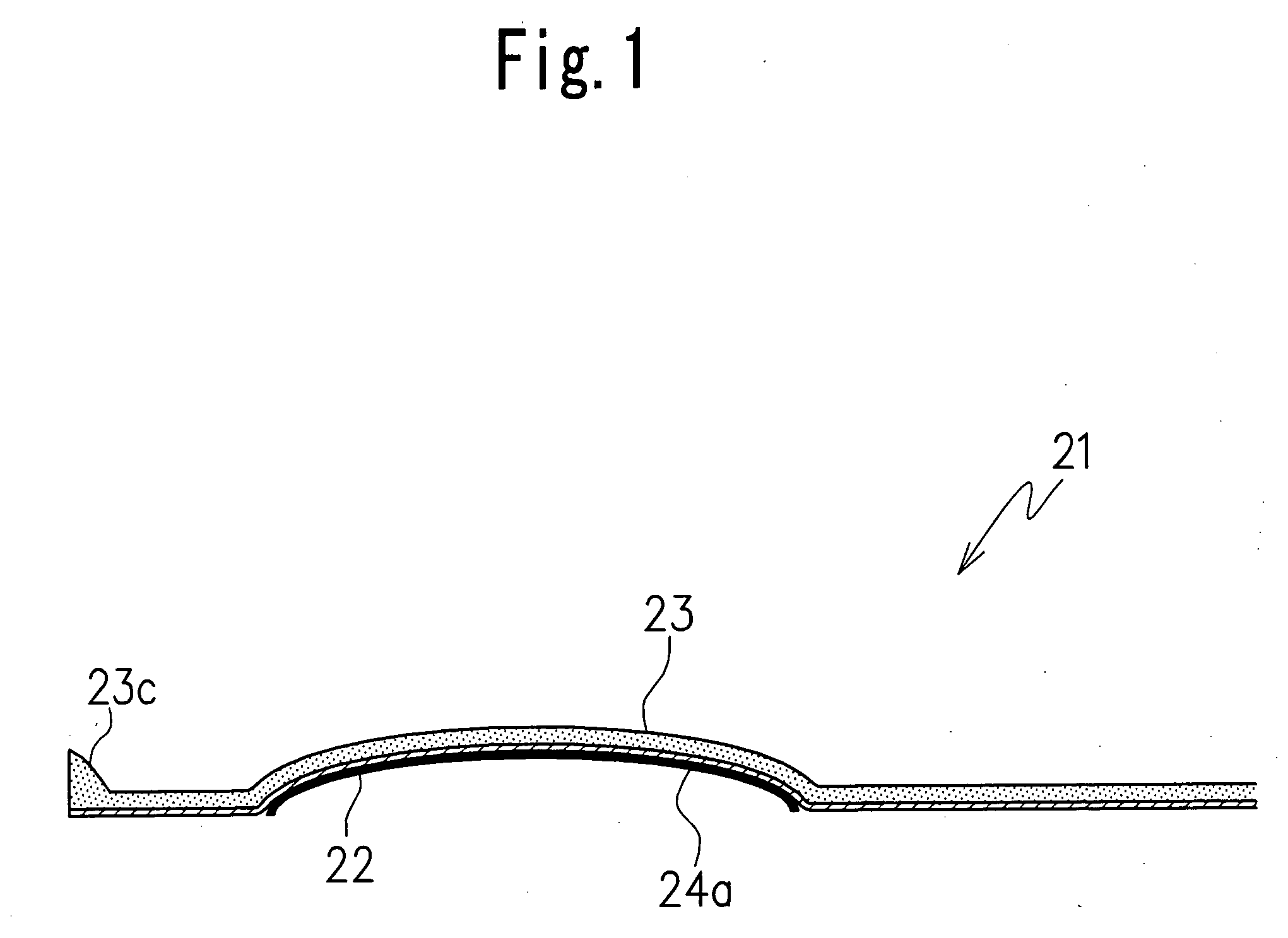
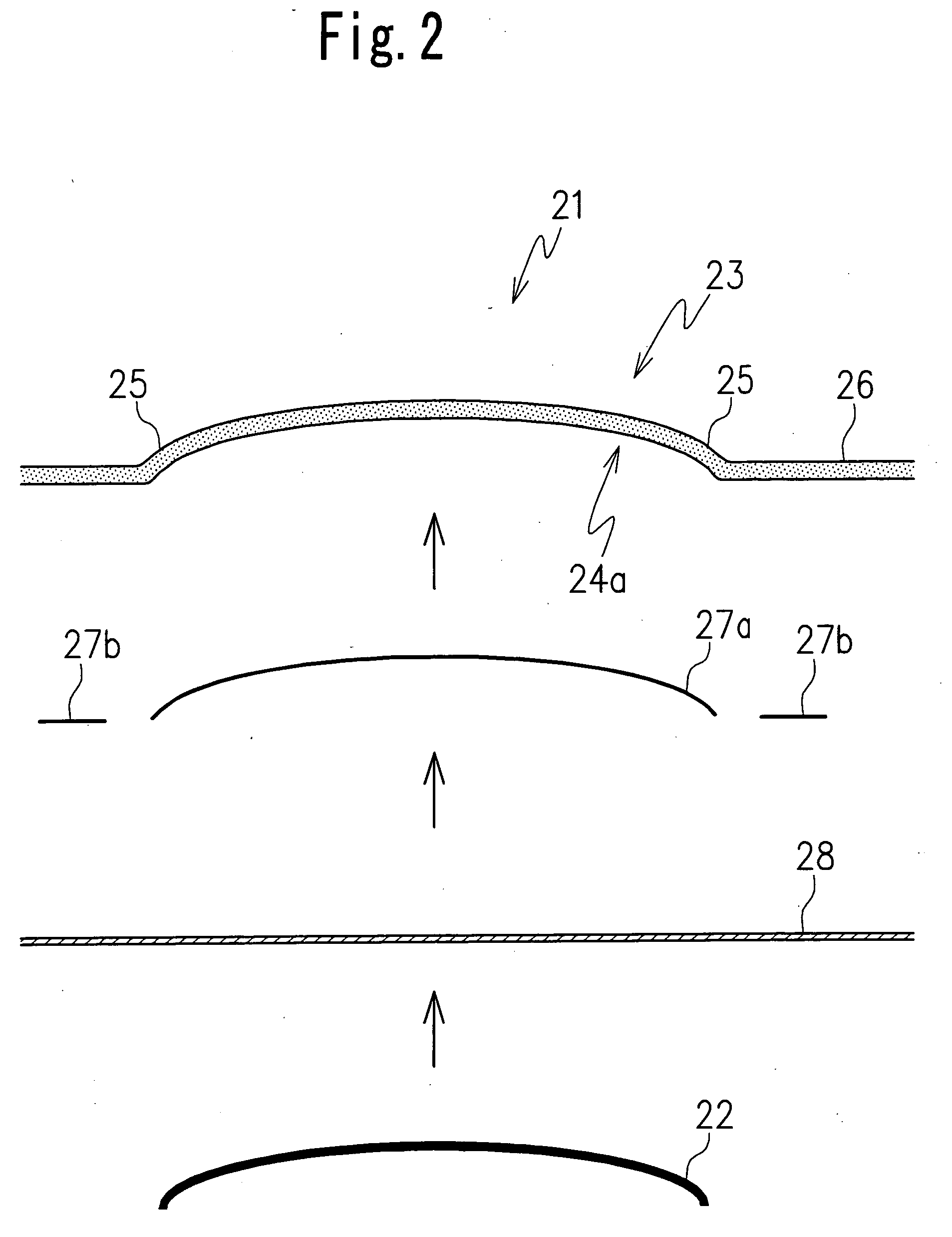
[0047] One embodiment of a sheet switch 21 according to the present invention and a sheet switch module to which the sheet switch is applied are first explained referring to FIGS. 1 to 5.

[0048] As shown in FIGS. 1 and 2, the sheet switch 21 according to the present invention includes a spring 22 configured to enable electrical conduction between a central contact 32 (see FIG. 5) which is provided on, for example, a circuit board 33 and a circumferential contact 20 (see FIG. 6) which is disposed circumferentially of the central contact 32, and a transparent sheet member 23 configured to cover the spring 22. The circumferential contact 20 is provided on the circuit board 33 to form electric patterns in combination with the central contact 32.

[0049] The spring 22 is disposed on the circumferential contact to face the central contact 32 and configured to enable electrical conduction between the central contact 32 and the circumferential contact 20 when an upper surface of the spring is...

second embodiment

[0070] the sheet switch module 31 according to the present invention is shown, with reference to FIGS. 6 to 9.

[0071] It should be noted that in several of the embodiments described hereinafter, identical reference numbers are attached to parts which are the same as those in the above-mentioned first embodiment.

[0072] The sheet switch module 31 in the second embodiment includes one or mole switch portions. Each of the switch portions includes electrode patterns having at least one central contact 32 disposed on one surface, for example, an upper surface of a circuit board 33 and at least one circumferential contact 20 disposed circumferentially of the central contact 32, and a spring 22 disposed on the circumferential contact over the central contact 32. In addition, connectors and so on (not shown) are provided on the circuit board 33. The circuit board 33 comprises a flexible printed circuit board (FPC) similar to that in the first embodiment.

[0073] Each of the springs 22 has an ...

third embodiment

[0091]FIG. 11 illustrates the sheet switch module according to the present invention.

[0092] The sheet switch module 51 in this embodiment has a structure in which at least one LED 52 is disposed at an end portion of a light guiding sheet 56 and one or more LEDs 53 are disposed at places other than the end portion of the light guiding sheet 56 to achieve an increased intensity of light.

[0093] The sheet switch module 51 includes concave portions provided in the light guiding sheet 56 for containing the LEDs 52 and 53. The concave portions are formed by a cutout 36 (see FIG. 11) provided in end portions of the light guiding sheet 56 and a hole 37 (see FIG. 17) provided in parts of the light guiding sheet other than the end portions. A side surface emission-type LED is used for the LED 52 disposed in the cutout 36, and an upper surface emission-type LED is used for the LED 53 disposed in the hole 37 to emit equally in all directions. Moreover, filling in a gap between an inner peripher...


PUM


Abstract

A sheet switch module including a sheet switch (21) having a central contact (32) disposed on a circuit board (33), a circumferential contact (20) disposed circumferentially of the central contact (32), a spring (22) disposed above the central contact (32), and a transparent sheet member (23) configured to cover the spring (22), the sheet switch (21) forming a switching circuit such that the spring (22) provides electrical conduction between the central contact (32) and the circumferential contact (20) when the sheet member is pressed, the sheet member (23) being formed by a light guiding sheet (30) configured to guide light emitted from an LED (34) along an upper surface of the spring (22).

Description

CROSS-REFERENCE TO THE RELATED APPLICATIONS [0001] This application is based on and claims priority from each of Japanese Patent Application No. 2005-239129, filed on Aug. 19, 2005, and Japanese Patent Application No. 2005-274618, filed on Sep. 21, 2005, the contents of which are incorporated herein by reference. BACKGROUND OF THE INVENTION [0002] 1. Field of the Invention [0003] The present invention relates to a sheet switch to be used for a thinned electronic instrument such as a mobile phone or the like, a sheet switch module which is configured to add an illumination function to the sheet switch and a panel switch in which the sheet switch module is installed. [0004] 2. Description of Related Art [0005] A conventional key switch provided in an operational panel installed in each of various electronic instruments such as mobile phones, mobile information terminals, or the like, often includes a key top disposed to allow for pressing of each of a plurality of springs and an illum...

Claims


Application Information

Patent Timeline
Patent Type & Authority Applications(United States)
IPC IPC(8): H01H9/00
CPCH01H13/83H01H2205/016H01H2221/07H01H2219/044H01H2219/062H01H2215/036
Inventor AIHARA, KENSHIMIYASHITA, ISAO
Owner CITIZEN ELECTRONICS CO LTD
Why Eureka
Try Eureka