Wind power generator

a wind power generator and wind power technology, applied in the field of wind power generators, can solve the problems of reducing the efficiency of the generator and creating turbulence, and achieve the effects of maximizing the overall efficiency of the wind power generator, cost-effective, and easy assembly

Inactive Publication Date: 2006-08-22
GRUBB KELLY W
View PDF13 Cites 37 Cited by
  • Summary
  • Abstract
  • Description
  • Claims
  • Application Information

AI Technical Summary

Benefits of technology

[0010]It is a main object of the present invention to provide a wind power generator which increases the velocity of air passing a propeller of the wind power generator.
[0011]It is another object of the present invention to provide a wind power generator which increases the velocity of air passing a propeller of the wind power generator without creating an undue amount of turbulence in the flowing fluid.SUMMARY OF THE INVENTION
[0013]The wind power generator embodying the present invention makes maximum use of any wind flowing through the generator and has the rotor blades to be located at the location of maximum efficiency for the fluid flowing through the generator. In this manner, the overall efficiency of the wind power generator is maximized. Furthermore, the wind power generator embodying the present invention is easy to assemble and thus is cost effective and does not create an undue amount of turbulence in the fluid flowing therethrough.

Problems solved by technology

Such turbulence may decrease the efficiency of the generator.
Many known wind power generators have elements that may create turbulence in the fluid flowing through the device.

Method used


Image

  • Wind power generator
  • Wind power generator

Examples


Embodiment Construction

[0017]Other objects, features and advantages of the invention will become apparent from a consideration of the following detailed description and the accompanying drawings.

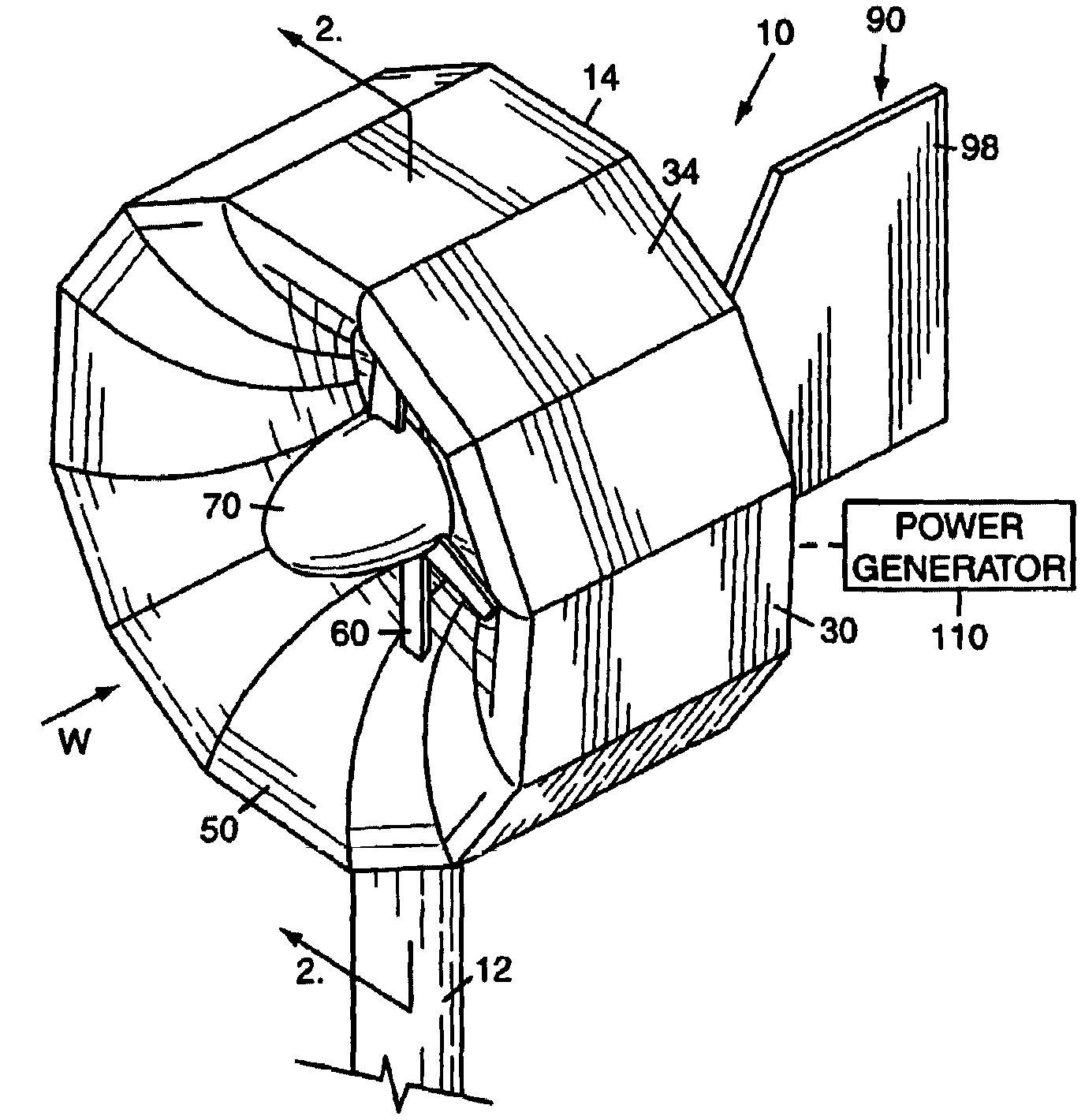
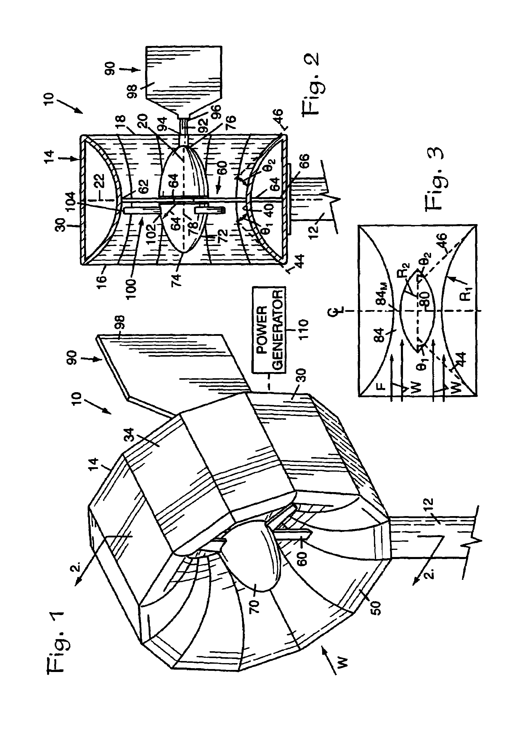
[0018]Referring to the Figures, it can be understood that the present invention is embodied in a wind power generator 10. Power generator 10 comprises a support element 12, such as a support post or the like, that is mounted on a support surface such as the ground and which extends upwardly therefrom.

[0019]An outer casing 14 is mounted on the support element 12 to be exposed to wind W flowing toward generator 10. Outer casing 14 has a first end 16 which is a fluid inlet end when the outer casing 14 is in use as shown in FIG. 1, a second end 18 which is an outlet end when the outer casing 14 is in use, a central axis 20 which extends between the first end 16 and the second end 18, and a central plane 22 which is located midway between the first end 16 of the outer casing 14 and the second end 18 of the outer casing...


PUM


Abstract

A wind power generator has an arcuate converging-diverging flow passage and a support body that is prolate in shape and is located in the flow passage. The support body is rotatably supported and a plurality of rotor blades are mounted on the support body. The support body and the flow passage define a converging-diverging flow area through which wind passes to drive the support body via the rotor blades.

Description

BACKGROUND OF THE INVENTION[0001]1. Field of the Invention[0002]The present invention relates to the general art of power generation, and to the particular field of wind power generators.[0003]2. Discussion of the Related Art[0004]Wind power generators have been known for centuries. Windmills have been used to operate machinery, produce power and the like for many years.[0005]Recently, interest in wind power generators has increased because wind is a cheap natural resource. Therefore, the technology associated with wind power generators has developed many systems that are more effective in producing power than the windmills of past generations.[0006]It is well understood that the amount of power that a wind power generator using a propeller can generate is proportional to the velocity of the wind flowing past the propeller. In fact, some relationships make this proportionality a cube of the wind velocity.[0007]Therefore, there is a need for a wind power generator which increases the...

Claims


Application Information

Patent Timeline
Patent Type & Authority Patents(United States)
IPC IPC(8): F03D7/02F03D1/04F15D1/02
CPCF03D1/04Y10S415/908Y02E10/72F05B2250/50Y02E10/728F03D13/20
Inventor GRUBB, KELLY W.
Owner GRUBB KELLY W
Why Eureka
Try Eureka