Low-profile power-generating wind turbine

a power-generating wind turbine and low-profile technology, applied in the direction of electric generator control, machines/engines, liquid fuel engines, etc., can solve the problems of large height of both types of wind turbines, disadvantageous limitation of the requirement of fixed locations of such known wind turbines, and inability to use safely at large heights

Active Publication Date: 2011-07-21
JORY CASSANDRA
View PDF38 Cites 19 Cited by
  • Summary
  • Abstract
  • Description
  • Claims
  • Application Information

AI Technical Summary

Benefits of technology

[0006]The requirement of such known wind turbines that they have fixed locations is a disadvantageous limitation of them. Also, their considerable-to-large height limits the places where they can be used safely or without objection to their appearance.

Problems solved by technology

Also, both of those kinds of wind turbines have considerable height.
The requirement of such known wind turbines that they have fixed locations is a disadvantageous limitation of them.
Also, their considerable-to-large height limits the places where they can be used safely or without objection to their appearance.

Method used


Image

  • Low-profile power-generating wind turbine
  • Low-profile power-generating wind turbine
  • Low-profile power-generating wind turbine

Examples


Embodiment Construction

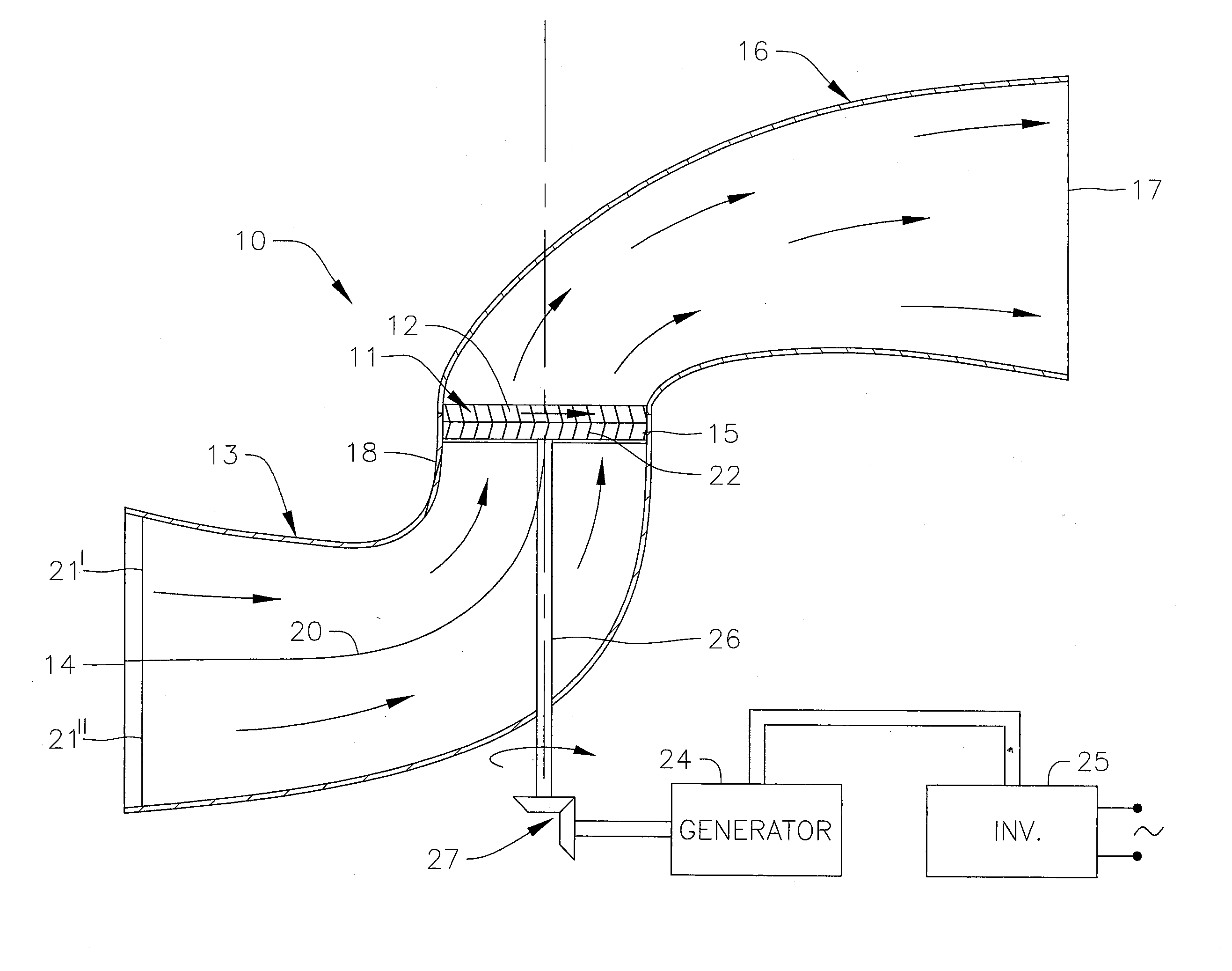
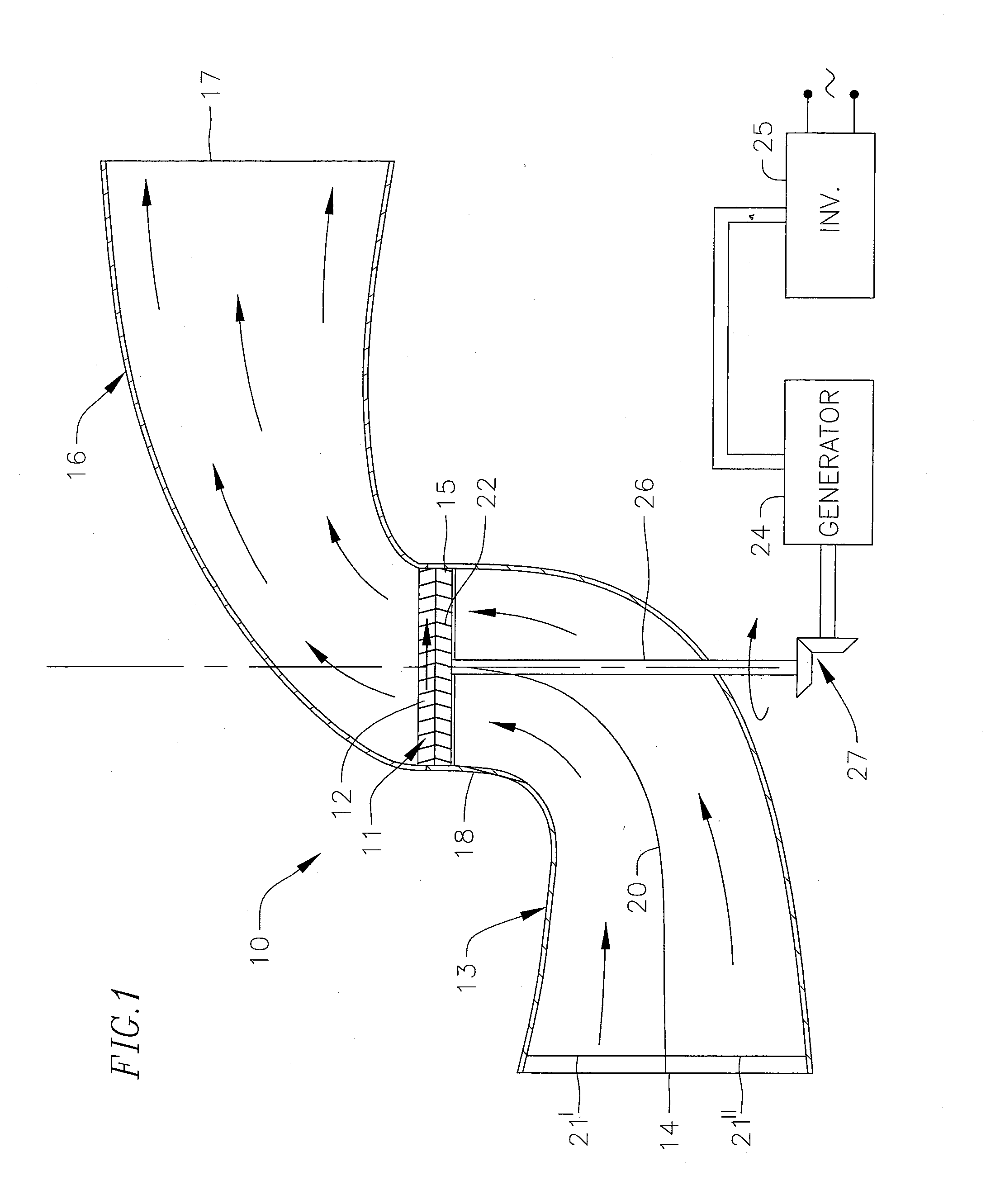
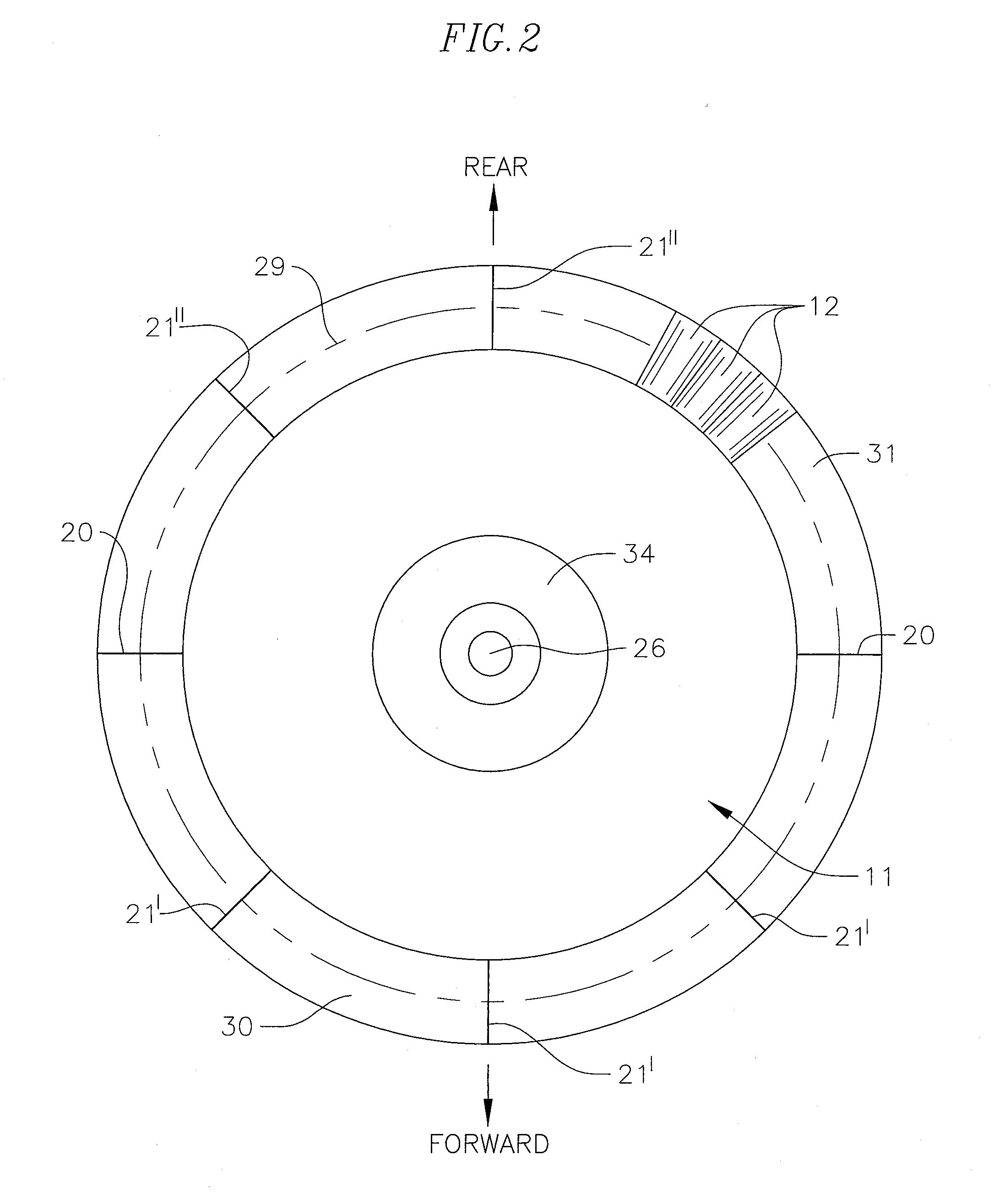
[0021]FIG. 1 is presented to illustrate principles of the operation and structure of a wind turbine according to this invention. FIG. 1 shows a low-profile power-generating wind turbine 10 in simplified and somewhat idealized form. The turbine includes a round rotor 11 which carries around its circumference a plurality of regularly spaced radially extending blades 12 of desired length and shape. The rotor is positioned for rotation in a plane which is substantially parallel to an outlet end 15 an inlet air flow passage 13 which has an inlet end 14 spaced in an upstream direction along the inlet passage from the rotor. An optional outlet air flow passage 16 can have an outlet end 17 spaced in a downstream direction from the rotor.

[0022]The portion 18 of the inlet passage 13 closely adjacent the rotor on its upstream side preferably is straight, of substantially constant diameter, and aligned with the rotor axis of rotation; that portion of the passage defines a passage throat. Passag...


PUM


Abstract

A wind turbine is disclosed which uses energy in air moving relatively toward the turbine to focus and increase the velocity of air entering a turbine inlet air flow passage. The inlet flow passage discharges focused and accelerated air to blades of a rotor where the blades interact with that air to turn the rotor. Rotor motion can be used to operate an electrical generator. The plane of rotation of the rotor can be at substantially right angles to the plane of the passage inlet opening. Baffles in the flow passage and stator vanes adjacent the rotor blades cause the mass flow of the accelerated air to be substantially uniform, and desirably directed, throughout the rotor's blade area. The turbine is compact and operates quietly.

Description

CROSS-REFERENCE TO REFERENCE TO RELATED APPLICATION[0001]This application claims the benefit of U.S. Provisional Application No. 61 / 296,280, filed Jan. 19, 2010.FIELD OF THE INVENTION[0002]This invention pertains to wind turbines which have low profiles, which are quiet when operating, and which can be used for generating electrical power. More particularly, the invention pertains to such wind turbines which collect ambient wind air and concentrate and direct that air to and through a radially - bladed rotor at a throat of a turbine air inlet passage.BACKGROUND OF THE INVENTION[0003]It is known to generate electrical power by use of wind-powered mechanisms. Known mechanisms for such purposes generally are of two kinds, namely, wind turbines which commonly have rotors resembling aircraft propellers which rotate about horizontal axes, and vertical axis wind turbines which commonly have long vertically extending blades as components of a cylindrical rotor. The rotors of those two kinds...

Claims


Application Information

Patent Timeline
Patent Type & Authority Applications(United States)
IPC IPC(8): F03D9/00F03D1/04
CPCF03D1/04F03D1/065F05B2240/13F03D9/002Y02E10/721Y02E10/725Y02B10/30F03D9/25B60K16/00F03D15/10Y02E10/72
Inventor STEINLECHNER, JOHANN
Owner JORY CASSANDRA
Why Eureka
Try Eureka