Air cleaner

a technology of air cleaners and air filters, applied in the field of air cleaners, can solve the problems of pollutants easily trapped in rooms, and achieve the effects of enhancing the air environment in a position in a room, reducing the amount of air current uselessly sent out, and enhancing the cleaning

Inactive Publication Date: 2010-07-29
SHARP KK
View PDF15 Cites 18 Cited by
  • Summary
  • Abstract
  • Description
  • Claims
  • Application Information

AI Technical Summary

Benefits of technology

[0040]As described above, according to the present invention, an effect of improving an air environment in a position in a room, away from an air cleaner, can be enhanced and an indoor air in a wide range can be effectively cleaned. In addition, since an air current uselessly sent out can be decreased, even when an amount of an air flow volume is small, a desired effect of improving the air environment can be attained. Since the same effect of improving the air environment can be realized even with a small amount of the air flow volume, a noise can be reduced. Further, in a case where gaps are present in windows and others provided in wall surfaces and airtightness of the room is low, an air velocity in the vicinity of a wall surface of the room can be increased, thereby attaining a positive pressure effect and allowing a reduction in an amount of dust intruding into the room from an outside of the room.

Problems solved by technology

In recent years, since houses have been rendered highly airtight, pollutants are easily trapped in rooms.
This is posing serious problems such as a sick house syndrome caused by volatile organic compounds and allergic symptoms caused by house dust.

Method used


Image

  • Air cleaner
  • Air cleaner
  • Air cleaner

Examples


first embodiment

Embodiment 1-1

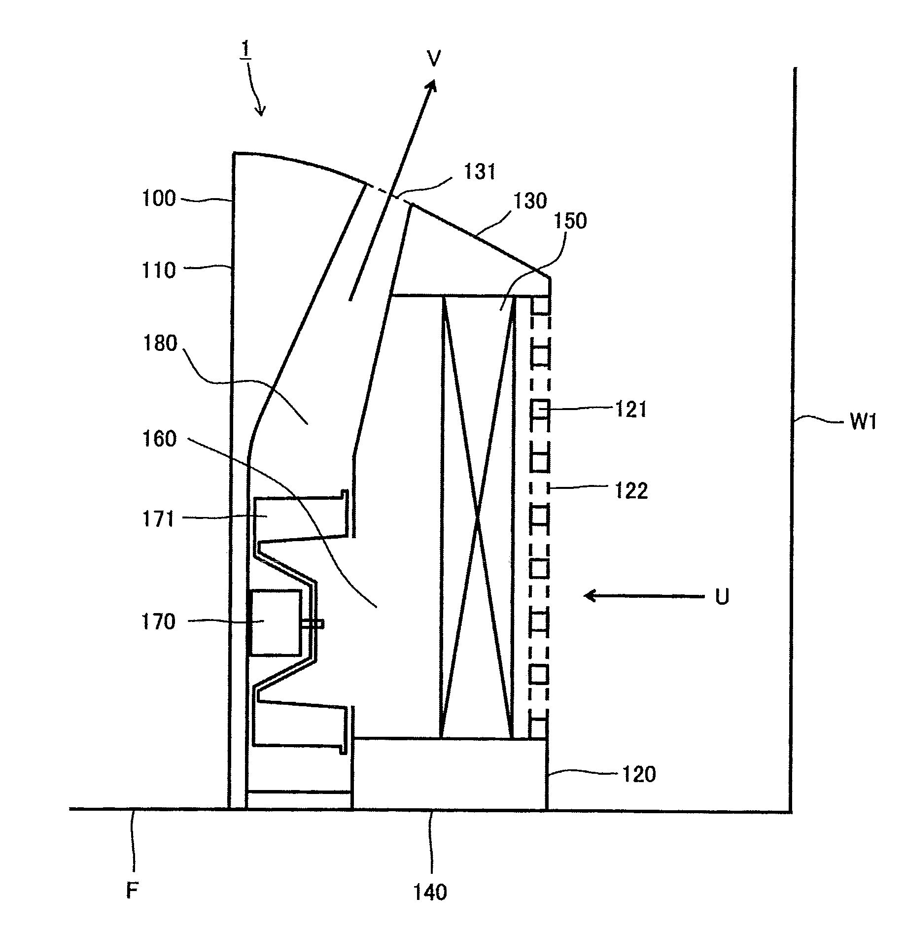
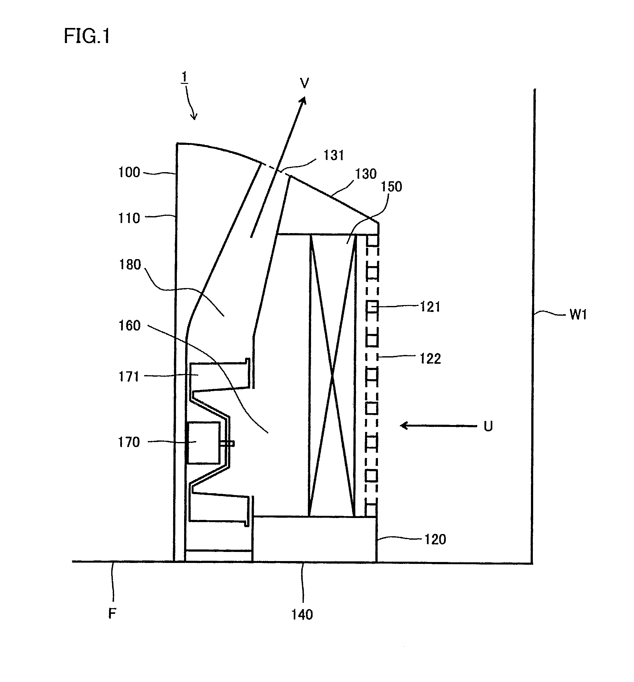
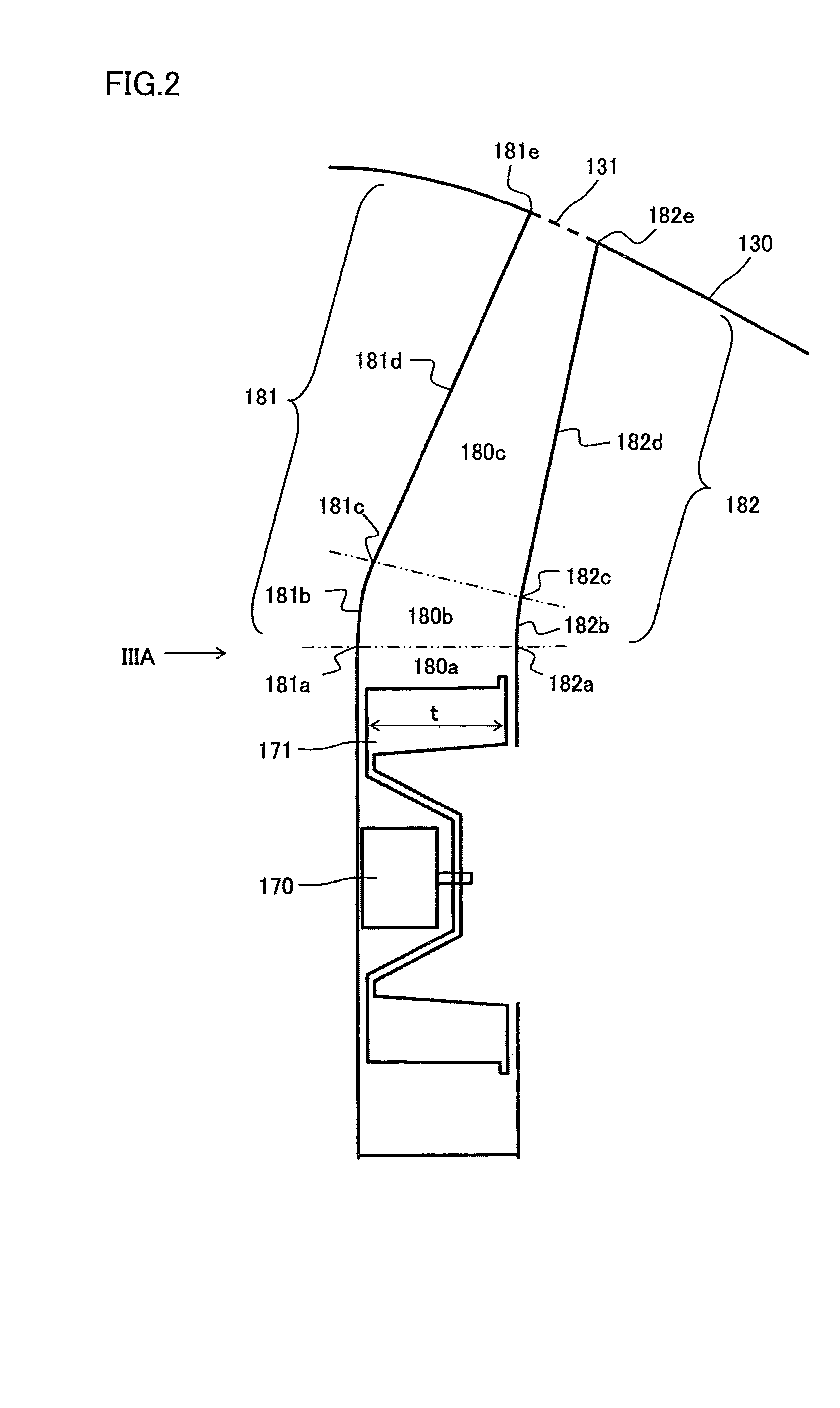
[0077]Hereinafter, an embodiment 1-1 of the present invention will be described with reference to drawings. FIG. 1 is a side sectional view schematically illustrating an air cleaner of the present embodiment. FIG. 2 is a partial side sectional view illustrating a blowout flow passageway of the air cleaner shown in FIG. 1 in an expanded manner. FIG. 3 is a cross-sectional view (A) illustrating the blowout flow passageway, taken from a IIIA direction in FIG. 2 and a cross-sectional view (B) showing a relationship of angles in the blowout flow passageway shown in FIG. 2.

[0078]As shown in FIG. 1, the air cleaner 1 is placed on a floor surface F or a desk and used so as to be located in the vicinity of a side wall surface W1 of a room. The air cleaner 1 comprises: a main body; a suction port 122 provided in the main body and for taking in air inside the room; an air filter 150 provided in the main body as a removing part for removing dust and / or a substance present in the a...

embodiment 1-2

[0203]Hereinafter, an embodiment 1-2 according to the present invention will be described with reference to drawings. FIG. 24 is a side cross-sectional view schematically illustrating an air cleaner of the embodiment 1-2.

[0204]As shown in FIG. 24, the air cleaner 2 is placed on a floor surface F or a desk and used so as to be located in the vicinity of a side wall surface W1 of a room. The air cleaner 2 comprises: a main body; a suction port 222 provided in the main body and for taking in air inside the room; an air filter 250 provided in the main body as a removing part for removing dust and / or a substance present in the air taken in from the suction port 222; a blowout port 231 provided in the main body and for sending out the air treated by the air filter 250 into the room; and an air blower 270 provided in the main body as an air blowing part for moving the air from the suction port 222 to the blowout port 231.

[0205]The main body of the air cleaner 2 is held by a housing 200. Th...

second embodiment

Embodiment 2-1

[0212]Hereinafter, an embodiment 2-1 of the present invention will be described with reference to drawings. FIG. 25 is a side cross-sectional view schematically illustrating an air cleaner of the embodiment 2-1. The same reference numerals as those used in the above descriptions of the embodiment 1-1 shown in FIG. 1 through FIG. 3 are used to denote the same parts as those in the embodiment 1-1.

[0213]As shown in FIG. 25, in the air cleaner 3 according to the present embodiment, a top surface 130 of a housing 100 is formed by a first top surface on a side of a front surface 110 on which an operation part 190 is provided and by a second top surface on a side of a rear surface 120 on which a blowout port 131 is provided. The operation part 190 is arranged on the side of the front surface 110 of the air cleaner 3 and used for switching an operation mode of the air cleaner 3. The blowout port 131 is arranged on the side of the rear surface 120 of the air cleaner 3 and used ...


PUM

PropertyMeasurementUnit
angleaaaaaaaaaa
distanceaaaaaaaaaa
flow passageway open angle α1aaaaaaaaaa

Abstract

Provided is an air cleaner capable of enhancing an effect of improving an indoor air environment through enhancing an efficiency of circulating an air current without increasing an air flow volume. The air cleaner (1) is placed on a floor surface (F) and used so as to be located in the vicinity of a side wall surface (W1) of a room and comprises a suction port (122), an air filter (150), a blowout port (131), and an air blower (170). When a distance from a middle position of the blowout port (131) to the side wall surface (W1) of the room is supposed to be L [mm], a distance from the middle position of the blowout port (131) to a ceiling surface of the room is supposed to be H [mm], and the air cleaner (1) is placed and used in a position which allows the distance L to be a value selected from among values in a range of 100<L<600, in order to cause the air sent out from the blowout port (131) to first reach the side wall surface (W1) of the room, an angle θ[°] formed between a direction in which the air is sent out from the blowout port (131) and a vertically upward direction is set to be in a range of tan−1(L/H)<θ≦35.

Description

TECHNICAL FIELD[0001]The present invention relates generally to air cleaners, and, more particularly, to an air cleaner which is placed on a floor or a desk and used so as to be located in the vicinity of a sidewall surface of a room.BACKGROUND ART[0002]In recent years, since houses have been rendered highly airtight, pollutants are easily trapped in rooms. This is posing serious problems such as a sick house syndrome caused by volatile organic compounds and allergic symptoms caused by house dust. Therefore, in order to improve an indoor air environment, an air cleaner and an air conditioner with an air cleaning function are used. In general, as a method for cleaning indoor air, a method in which pollutants are taken into an air cleaner by an air blower and removed by a filter is employed. On the other hand, in order to improve the indoor air environment, active researches have been conducted, devising a method in which instead of the filter, an electric dust collecting apparatus is...

Claims


Application Information

Patent Timeline
Patent Type & Authority Applications(United States)
IPC IPC(8): B01D46/00F24F7/00A61L9/00F24F8/80F24F1/035F24F1/0353F24F8/10
CPCF24F1/0071F24F3/1603F24F8/10F24F1/035F24F1/0353F24F8/80B01D46/00F24F13/08F24F7/003
Inventor TAKEDA, YASUKATAOHTSUKA, MASAKI
Owner SHARP KK
Why Eureka
Try Eureka