Laser cutter for tempered glass

A technology of laser cutting and tempered glass, applied in laser welding equipment, welding equipment, metal processing equipment, etc., can solve problems such as labor-intensive use, inconvenient maintenance and replacement, large gain over loss, etc., to improve versatility and facilitate Maintenance and replacement, the effect of purifying the air environment

Inactive Publication Date: 2018-01-09
SUZHOU MIKE LASER TECH SERVICE CO LTD
View PDF0 Cites 10 Cited by
  • Summary
  • Abstract
  • Description
  • Claims
  • Application Information

AI Technical Summary

Problems solved by technology

[0002] Tempered glass is actually a kind of prestressed glass. In order to improve the strength of glass, chemical or physical methods are usually used to form compressive stress on the glass surface. Wind pressure, cold and heat, and impact, etc., so the cutting efficiency of traditional cutting machines for tempered glass is slow, which delays the processing and production of tempered glass. For this reason, people invented laser cutting machines for tempered glass. cutting, which greatly improves the efficiency of cutting
[0003] Laser cutting is a machining method that uses high-power-density laser beams to irradiate materials to rapidly heat materials to vaporization temperature to form grooves. It has the advantages of good cutting quality, high cutting efficiency, and fast cutting speed. It is some The thermal cutting method commonly used for sheet metal parts; the indispensable conditions for generating laser light are particle

Method used


Image

  • Laser cutter for tempered glass
  • Laser cutter for tempered glass
  • Laser cutter for tempered glass

Examples


Example Embodiment

[0028] The technical solutions in the embodiments of the present invention will be clearly and completely described below with reference to the accompanying drawings in the embodiments of the present invention. Obviously, the described embodiments are only a part of the embodiments of the present invention, but not all of the embodiments. Based on the embodiments of the present invention, all other embodiments obtained by those of ordinary skill in the art without creative efforts shall fall within the protection scope of the present invention.
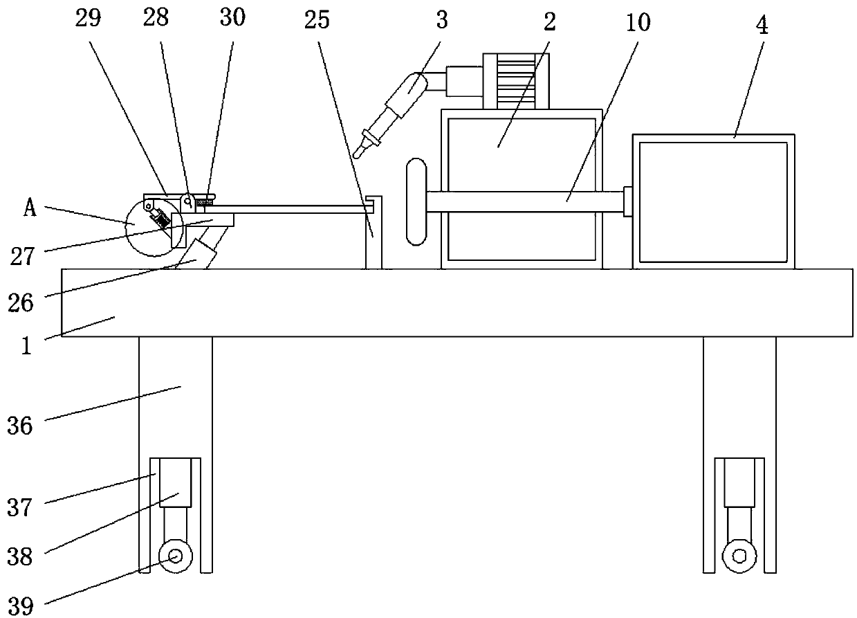
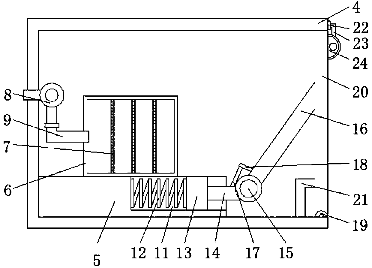
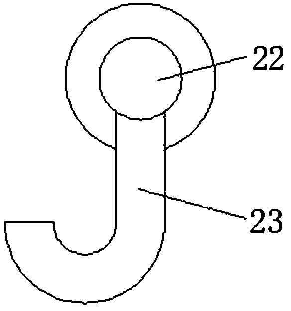
[0029] see Figure 1-4, a laser cutter for tempered glass, including a frame 1, a laser 2 is fixedly installed on one side of the top of the frame 1, a laser head 3 is fixedly installed on the top of the laser 2, and the material is cut by light, electricity and other methods. Excitation is performed so that some of the particles are excited to a state with higher energy. When the number of particles in this state is greater than the ...


PUM


Abstract

The invention discloses a laser cutter for tempered glass, which comprises a frame, an outer box is fixedly installed on the other side of the top of the frame, a connecting plate is fixedly installed inside the outer box, and one side of the inner wall of the outer box is fixed A blower is installed, a chute is opened inside the connecting plate, a first spring is fixedly installed on one side of the inner wall of the chute, a slider is fixedly connected to one end of the first spring, and a first connecting rod is welded on one side of the slider. One end of the first connecting rod is hinged with a second connecting rod through a first rotating shaft, and one side of the inner cavity of the outer box is hinged with a side plate through a second rotating shaft. The laser cutter for tempered glass, by setting the blower to suck the dust into the inside of the dust removal box, purifies the air environment in the factory and reduces the risk of dust inhalation by the staff. Under the elasticity of the first spring, the first The connecting rod cooperates with the second connecting rod so that the side plate can be opened automatically, thereby facilitating the maintenance and replacement of the dust removal box.

Description

technical field [0001] The invention relates to the technical field of laser equipment, in particular to a laser cutter for tempered glass. Background technique [0002] Tempered glass is actually a kind of prestressed glass. In order to improve the strength of glass, chemical or physical methods are usually used to form compressive stress on the glass surface. Wind pressure, cold and heat, and impact, etc., so the cutting efficiency of traditional cutting machines for tempered glass is slow, which delays the processing and production of tempered glass. For this reason, people invented laser cutting machines for tempered glass. Cutting, which greatly improves the efficiency of cutting. [0003] Laser cutting is a machining method that uses high-power-density laser beams to irradiate materials to rapidly heat materials to vaporization temperature to form grooves. It has the advantages of good cutting quality, high cutting efficiency, and fast cutting speed. It is some The t...

Claims


Application Information

Patent Timeline
IPC IPC(8): B23K26/38B23K26/402B23K26/16B23K26/70
Inventor 熊春霞李陶
Owner SUZHOU MIKE LASER TECH SERVICE CO LTD
Why Eureka
Try Eureka