System and method for pointing and control of an antenna

a technology of antennae and antenna wing, applied in the direction of antennas, antenna details, antenna adaptation in movable bodies, etc., can solve the problems of electrical system problems, unfavorable large-area antennae, and unfavorable large-area antenna

Active Publication Date: 2006-08-22
L3 TECH INC
View PDF6 Cites 87 Cited by
  • Summary
  • Abstract
  • Description
  • Claims
  • Application Information

AI Technical Summary

Problems solved by technology

The environment outside an aircraft, however, is not hospitable to most large area antennae.
As a result, the required antenna shape is usually not very aerodynamic.
The relatively high velocity air flow while an aircraft is in flight ca

Method used


Image

  • System and method for pointing and control of an antenna
  • System and method for pointing and control of an antenna
  • System and method for pointing and control of an antenna

Examples


Embodiment Construction

[0015]Reference will now be made to the exemplary embodiments illustrated in the drawings, and specific language will be used herein to describe the same. It will nevertheless be understood that no limitation of the scope of the invention is thereby intended. Alterations and further modifications of the inventive features illustrated herein, and additional applications of the principles of the inventions as illustrated herein, which would occur to one skilled in the relevant art and having possession of this disclosure, are to be considered within the scope of the invention.

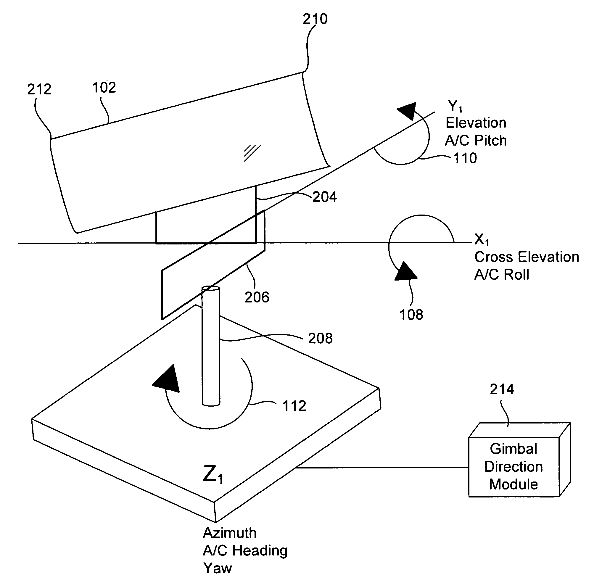
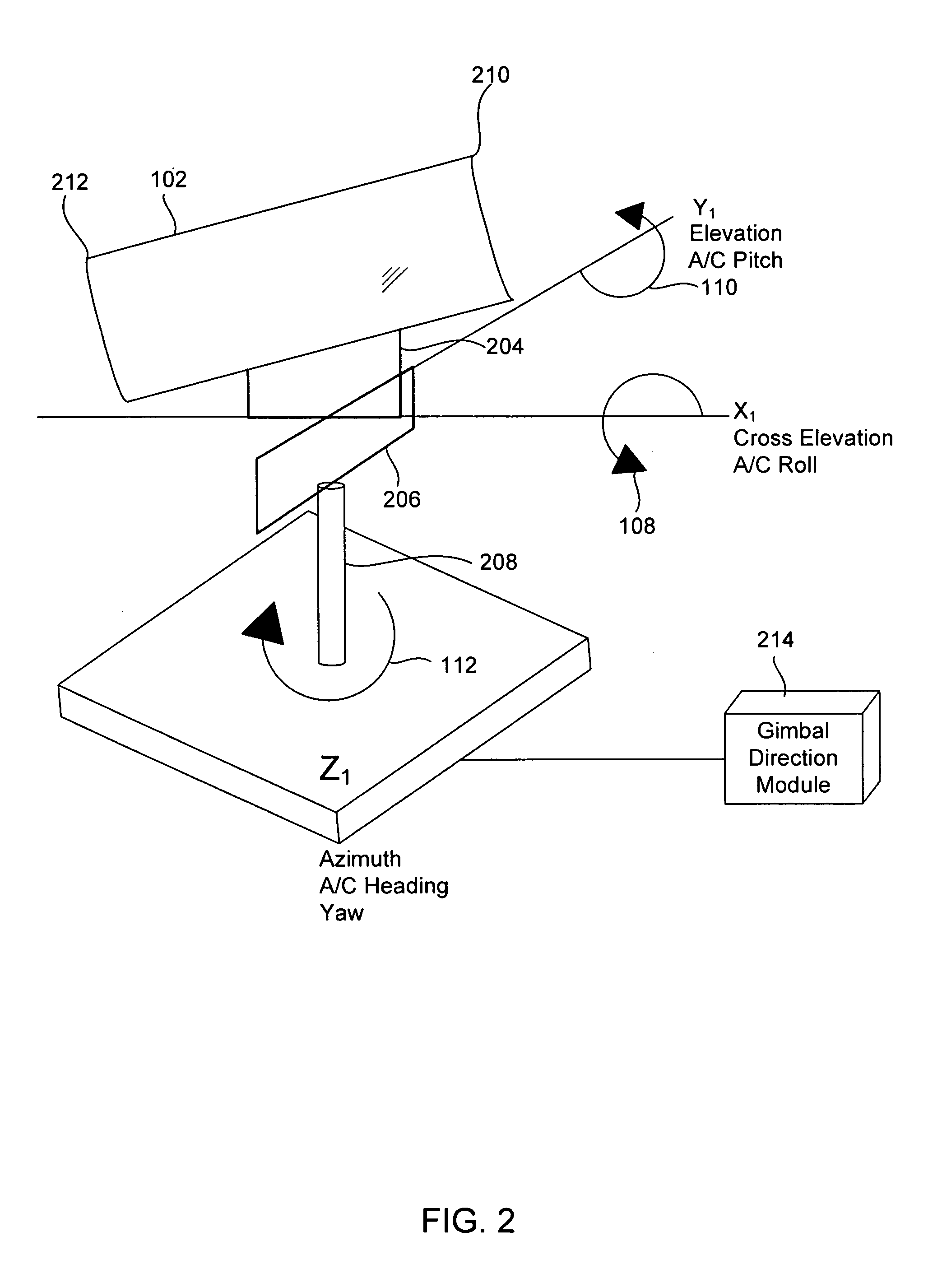
[0016]An antenna can be placed on a pedestal which can be used to control movement of the antenna with a plurality of gimbals. One gimbal can be used for each axis or dimension of movement desired. The gimbals can be controlled using electric motors. Accurate gimbal movement can be obtained using alternating current (AC) or direct current (DC) motors which can be electrically controlled using a gimbal direction m...


PUM


Abstract

A method is disclosed for directing an antenna mounted in a restricted radome on an aircraft. The method can include the operation of determining whether the antenna is directed in a keyhole. A further operation can involve controlling the antenna using an elevation gimbal and an azimuth gimbal when it is determined the antenna is directed outside the keyhole. Another operation can include directing the antenna using an elevation, azimuth, and cross elevation gimbal when it is determined the antenna is pointing in the keyhole.

Description

FIELD OF THE INVENTION[0001]The present invention relates generally to the directional control of antennae.BACKGROUND[0002]Some aircraft have the capability to communicate with satellites in various earth orbits, such as geosynchronous (GEO), low earth orbit (LEO), and polar orbit. Transmission of high data rates between aircraft and the satellites at a low power level requires a highly directive antenna with a large aperture area. Such a directive antenna strives to maintain accurate positioning to point the antenna in the direction of the satellite. The satellite is in constant motion in orbit around the earth. As the aircraft moves, it is subject to changes in latitude, longitude, and altitude. The aircraft's attitude, measured in roll, pitch and yaw, can also change relative to the satellite. A gimbaled antenna pedestal can be used to compensate for the movement of the satellite and changes in velocity, position, and attitude of the aircraft and allow the antenna mounted on the ...

Claims


Application Information

Patent Timeline
IPC IPC(8): H01Q3/08
CPCH01Q3/08H01Q1/125H01Q1/28
Inventor TIMOTHY, LAMAR K.SATO, JEFFREY S.BUCHANAN, ALAN M.BATZER, PATRICIA F.
Owner L3 TECH INC
Why Eureka
Try Eureka