
Sleeve device with stepped structure

a technology of stepping structure and sleeves, which is applied in the direction of wrenches, screwdrivers, manufacturing tools, etc., can solve the problems of inability to find suitable ones, inconvenient use, and inability to adapt sleeves to one kind of screw means, etc., and achieve the effect of convenient and convenient work

Inactive Publication Date: 2006-08-29
HSIEH CHIH CHING
View PDF7 Cites 7 Cited by
  • Summary
  • Abstract
  • Description
  • Claims
  • Application Information

AI Technical Summary

Benefits of technology

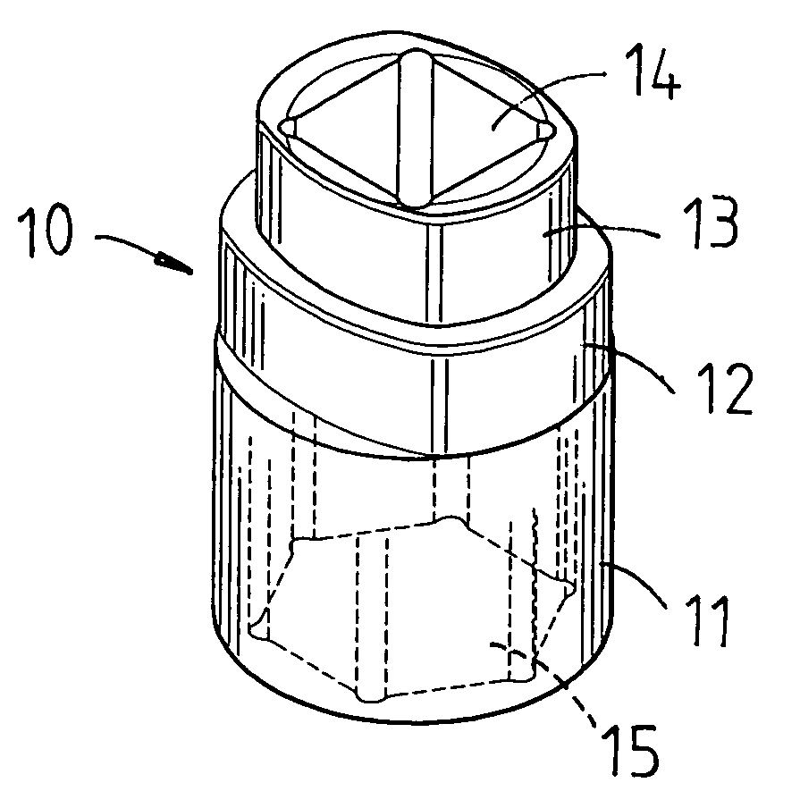
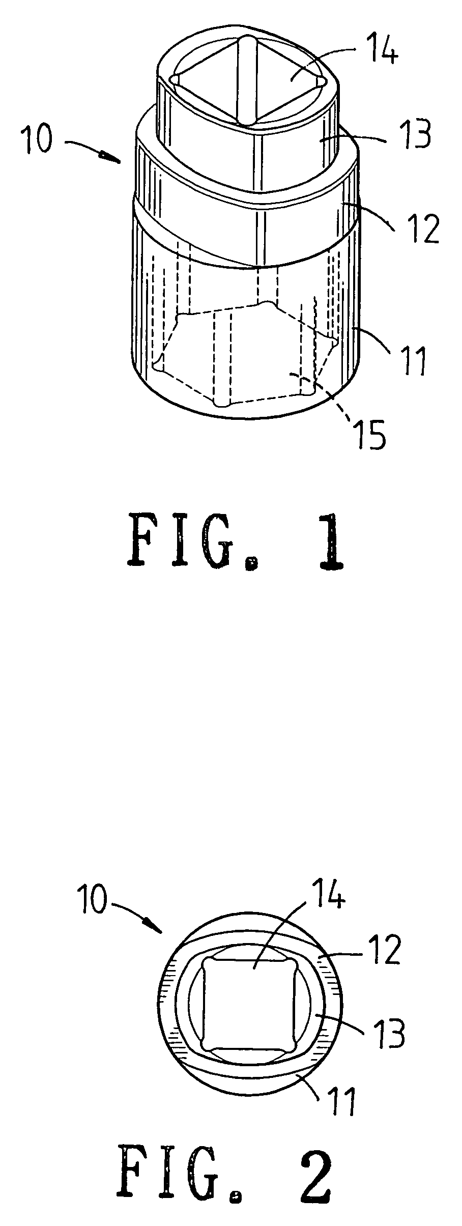
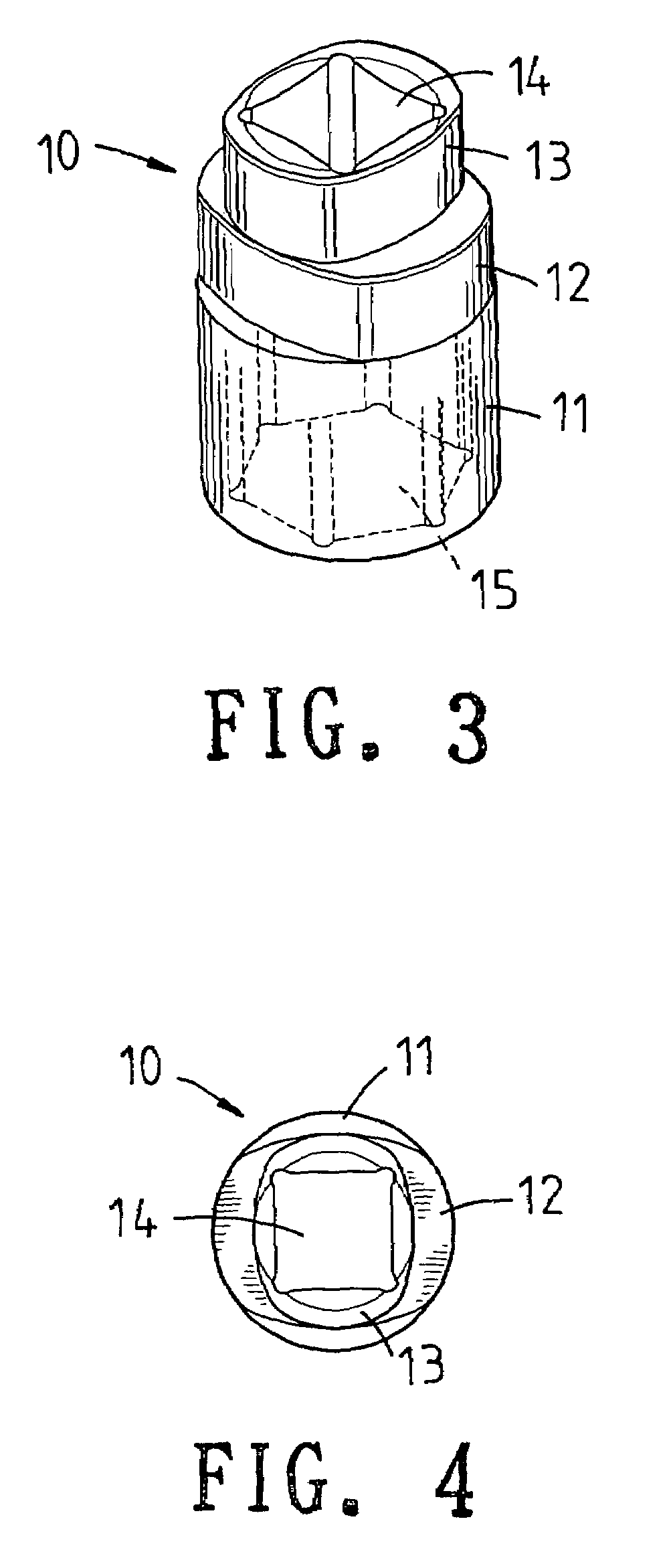
"The present invention provides a sleeve device with a stepped structure that is suitable for different kinds of spanners. This allows the user to easily and conveniently operate the sleeve device with different kinds of spanner. The sleeve device comprises a sleeve portion with a first opening and a first sleeve extending from the upper side of the sleeve portion. The sleeve portion has four sides, two opposite sides being suitable for one kind of spanner and the other two opposite sides being suitable for another kind of spanner. The first sleeve and the second sleeve are formed as a stepped structure, where the second sleeve has a second opening and is smaller in size than the first sleeve. The technical effect of the present invention is to provide a versatile and convenient tool for spanning different kinds of spanners."

Problems solved by technology

However generally, the sleeve is not suitable for one kind of screw means.
However this will make the work become tedious and even a suitable one cannot be found.
Moreover the prior art method of rotating the screw means is confined by the space.
Furthermore, the working time is prolonged.

Method used


Image

  • Sleeve device with stepped structure
  • Sleeve device with stepped structure
  • Sleeve device with stepped structure

Examples


first embodiment

[0020]Referring to FIGS. 5 and 6, the operation of the present invention is illustrated. In this embodiment, the orientation of the second sleeve 13 is parallel to that of the first sleeve 12. In use, the sleeve device 10 is engaged to a screwing means. A spanner 16 serves to clamp two opposite sides of the first sleeve 12 and then rotate the sleeve device 10. If no spanner 16 fits the two opposite sides of the first sleeve 12, a second spanner 16 is used to clamp two opposite sides of the second sleeve 13 or other two opposite sides of the first sleeve 12. Thereby the present invention provides more usages to users.

second embodiment

[0021]With reference to FIGS. 7 and 8, the present invention is illustrated. In this arrangement, the orientation of the second sleeve 13 is vertical to that of the first sleeve 12. The use of this embodiment provides the user to operate the present invention from different orientation.

[0022]Referring to FIGS. 9 and 10, it is illustrated that the present invention is used with an opener 17. The sleeve device is installed to one end of the opener 17. The first sleeve 12 and second sleeve 13 protrude out from one end of the opener 17. When the opener 17 is used to rotate or detach a screwing means. If a great force is necessary, a spanner clamps the first sleeve 12 or second sleeve 13 for rotating the sleeve device so as to detach the screwing means. Thereby the force can be applied easily so that the hand will not hurt or the opener will not be damaged.


PUM


Abstract

A sleeve device comprises a sleeve portion, the sleeve portion having a first opening; a first sleeve extending from an upper side of the sleeve portion; the sleeve portion having four sides; two opposite sides of the four sides being suitable for one kind of spanner and the other two opposite sides being suitable for another kind of spanner; a second sleeve; the sleeve portion having four sides; two opposite sides of the four sides being suitable for one kind of spanner and the other two opposite sides being suitable for another kind of spanner; the first sleeve and the second sleeve being formed as a stepped structure; the second sleeve having a second opening. The second sleeve has a shape similar to that of the first sleeve and the size of the second sleeve is smaller than that of the first sleeve.

Description

FIELD OF THE INVENTION[0001]The present invention relates to sleeve devices, and in particular a sleeve device with a stepped structure which is suitable for different kinds of spanners so that the user can operate the sleeve device with different kinds of spanner and thus the work can be performed easily and conveniently.BACKGROUND OF THE INVENTION[0002]Currently, in general, a spanner is used to rotate a screw means. If the spanner cannot apply a sufficient force to the screw means, a sleeve is used to cover upon the screw means and then a spanner is used to clamp the screw mean. Then a force is applied to the screw means through the sleeve. However generally, the sleeve is not suitable for one kind of screw means. If a suitable spanner cannot fit the sleeve, the user must search a new one. However this will make the work become tedious and even a suitable one cannot be found.[0003]Moreover the prior art method of rotating the screw means is confined by the space. Since the sleeve...

Claims


Application Information

Patent Timeline
Patent Type & Authority Patents(United States)
IPC IPC(8): B25B13/00
CPCB25B13/06B25G1/005B25B23/0035B25B15/02
Inventor HSIEH, CHIH-CHING
Owner HSIEH CHIH CHING
Learn More