Filter device
- Summary
- Abstract
- Description
- Claims
- Application Information
AI Technical Summary
Benefits of technology
Problems solved by technology
Method used
Image
Examples
Embodiment Construction
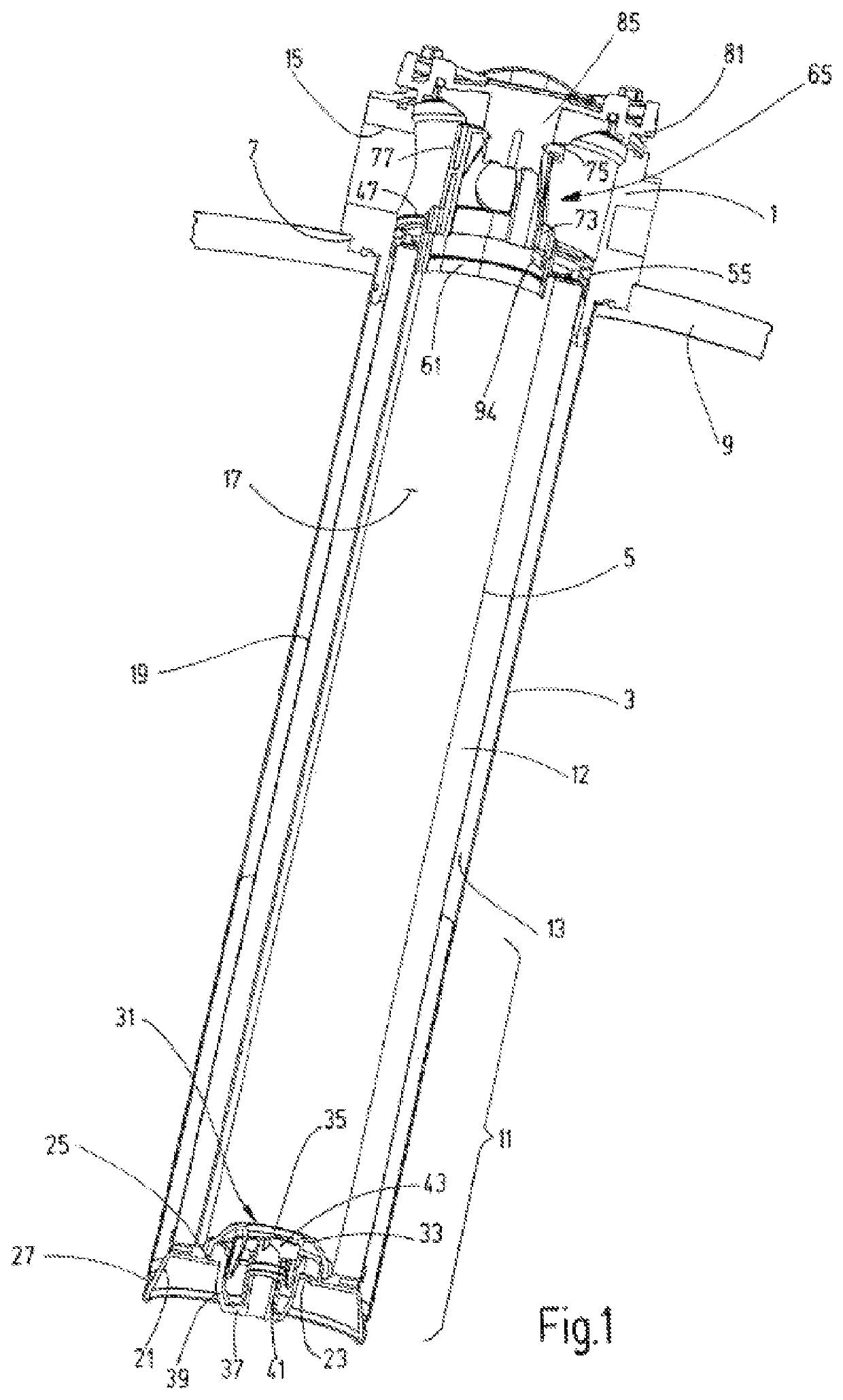
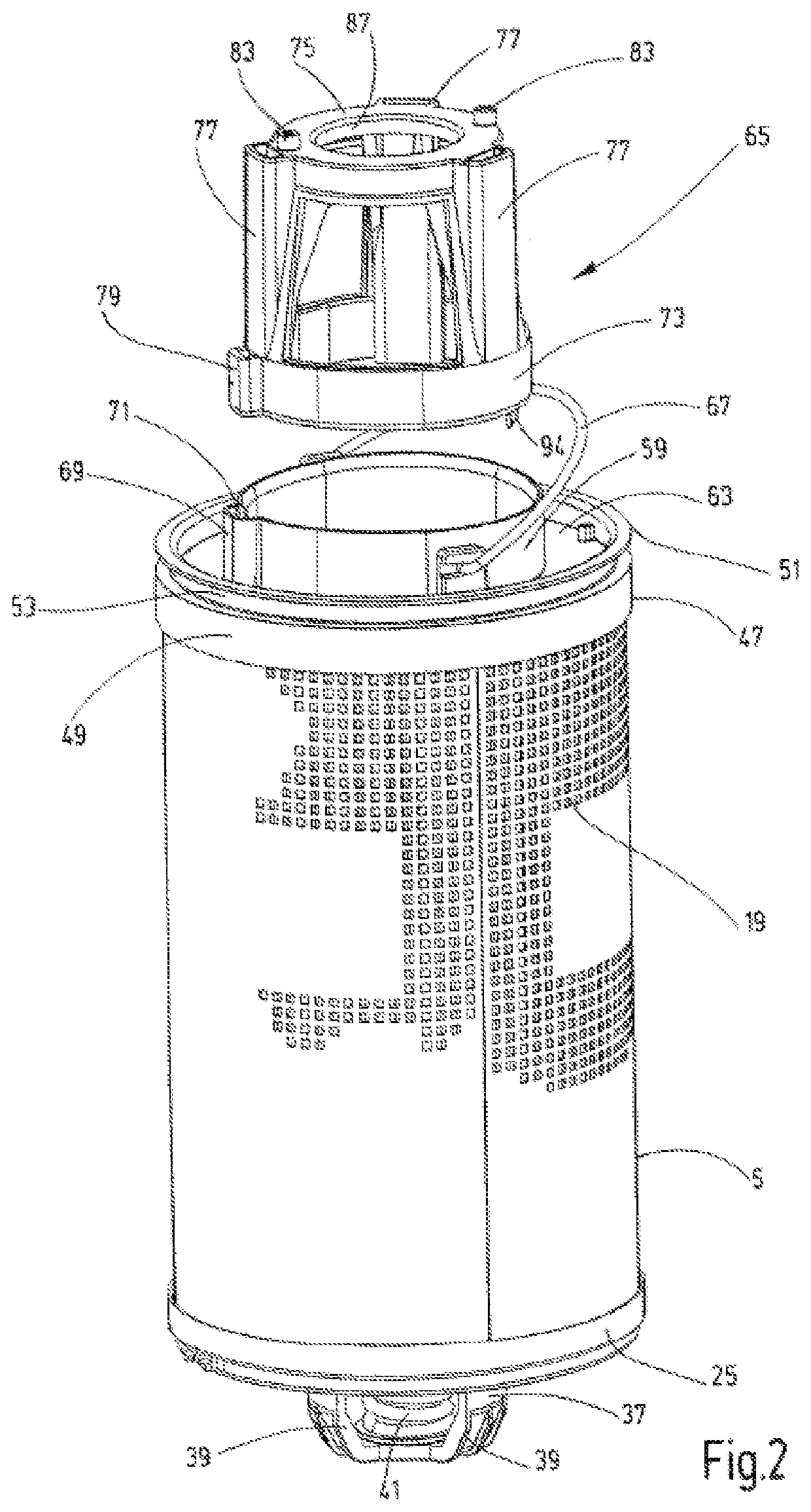
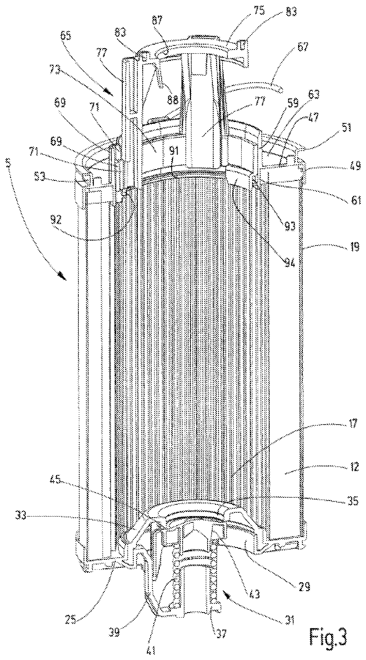
[0035]With reference to the attached drawings, the invention is described by way of example for tank-installation filter devices. In a first exemplary embodiment, a housing head 1, which in conjunction with an enclosure 3 forms the filter housing for receiving a filter element 5, is attached to an upper opening 7 in a tank 9, which is shown only schematically. The rest of the tank, holding a fluid supply, is not shown. As usual in the case of tank installation filter devices, the enclosure 3 is provided, at least in a lower length area 11, which is below the normal liquid level in the tank, with a perforation through which filtrate emerges from the chamber 13 in the filtering process. Chamber 13 is located between the outside of the filter material 12 of the filter element 5 and the enclosure 3 and forms the clean side during the filtration process. The inflow of the unfiltered matter is routed from a fluid inlet 15 in the housing head 1 to the inner filter cavity 17, which is encom...
PUM
| Property | Measurement | Unit |
|---|---|---|
| Length | aaaaa | aaaaa |
| Area | aaaaa | aaaaa |
| Height | aaaaa | aaaaa |
Abstract
Description
Claims
Application Information
 - R&D
- Intellectual Property
- Life Sciences
- Materials
- Tech Scout
- Unparalleled Data Quality
- Higher Quality Content
- 60% Fewer Hallucinations
Browse by: Latest US Patents, China's latest patents, Technical Efficacy Thesaurus, Application Domain, Technology Topic, Popular Technical Reports.
© 2025 PatSnap. All rights reserved.Legal|Privacy policy|Modern Slavery Act Transparency Statement|Sitemap|About US| Contact US: help@patsnap.com


