
Portable pipe outer diameter-chamfering apparatus with improved weldability

a technology of weldability and pipe, which is applied in the field of portable pipe outer diameterchamfering apparatus with improved weldability, can solve the problems of poor working environment, difficult chamfering work on the cutting surface of pipes in which pipes have been installed in the course of performing piping work, and the use of portable grinders such as portable grinders does not provide a regular chamfering angle, etc., to achieve convenient pipe chamfering, convenient portability, and simple structur

Active Publication Date: 2017-04-25
LEE JONG IL
View PDF20 Cites 3 Cited by
  • Summary
  • Abstract
  • Description
  • Claims
  • Application Information

AI Technical Summary

Benefits of technology

[0014]The present invention relates to a portable pipe outer diameter-chamfering apparatus for chamfering a cutting surface of a pipe. An object of the present invention is to solve the problems that, when the work of chamfering the cutting surface of pipes located in an elevated place during the plant piping work is manually performed, the work efficiency decreases and the work may be difficult. Another object of the present invention is to solve the problems that, in the case of using the pipe chamfering apparatus, the work is easy and can be easily and conveniently performed, but several chamfering apparatuses must be provided in compliance with the diameter of the pipe.
[0015]The chamfering apparatus of the present invention can perform chamfering by actively installing in accordance with the diameter of the pipe, thereby the pipe chamfering can be easily performed.
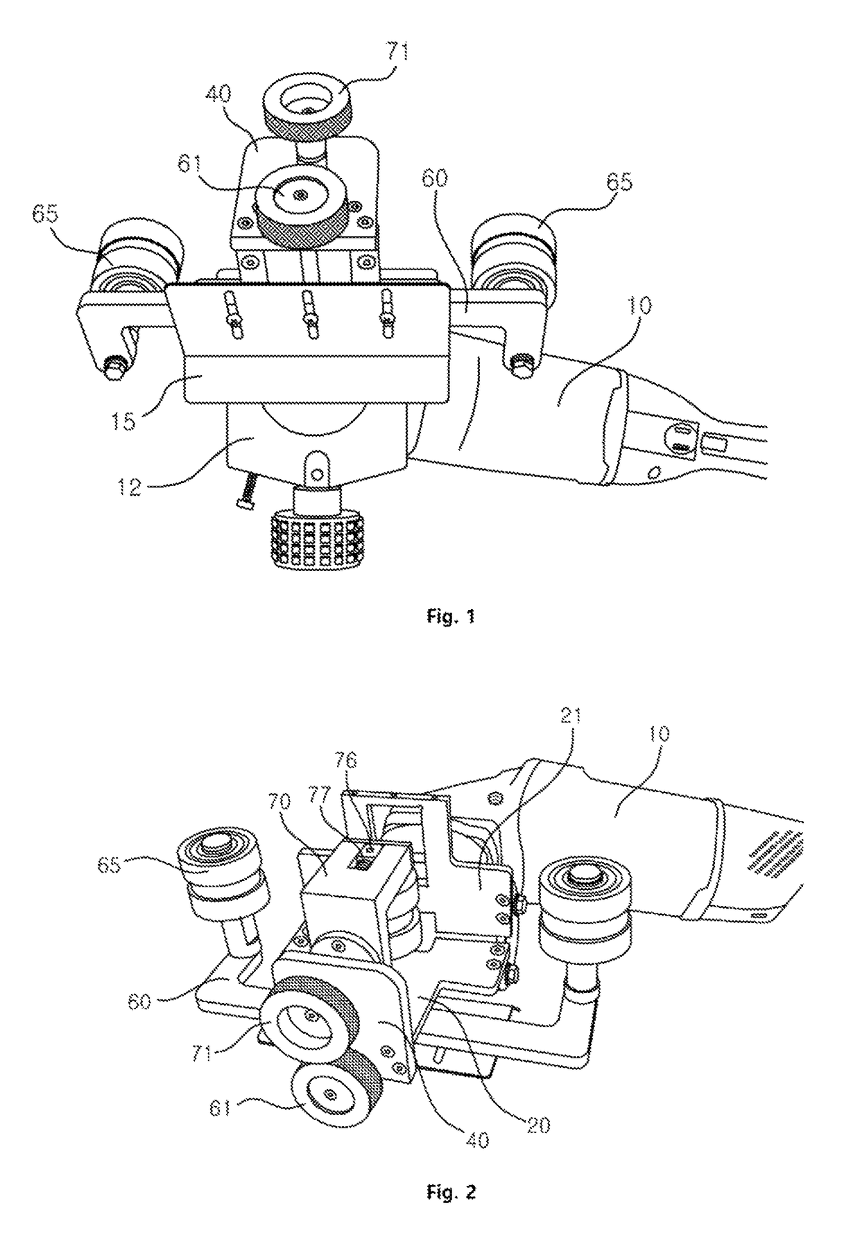
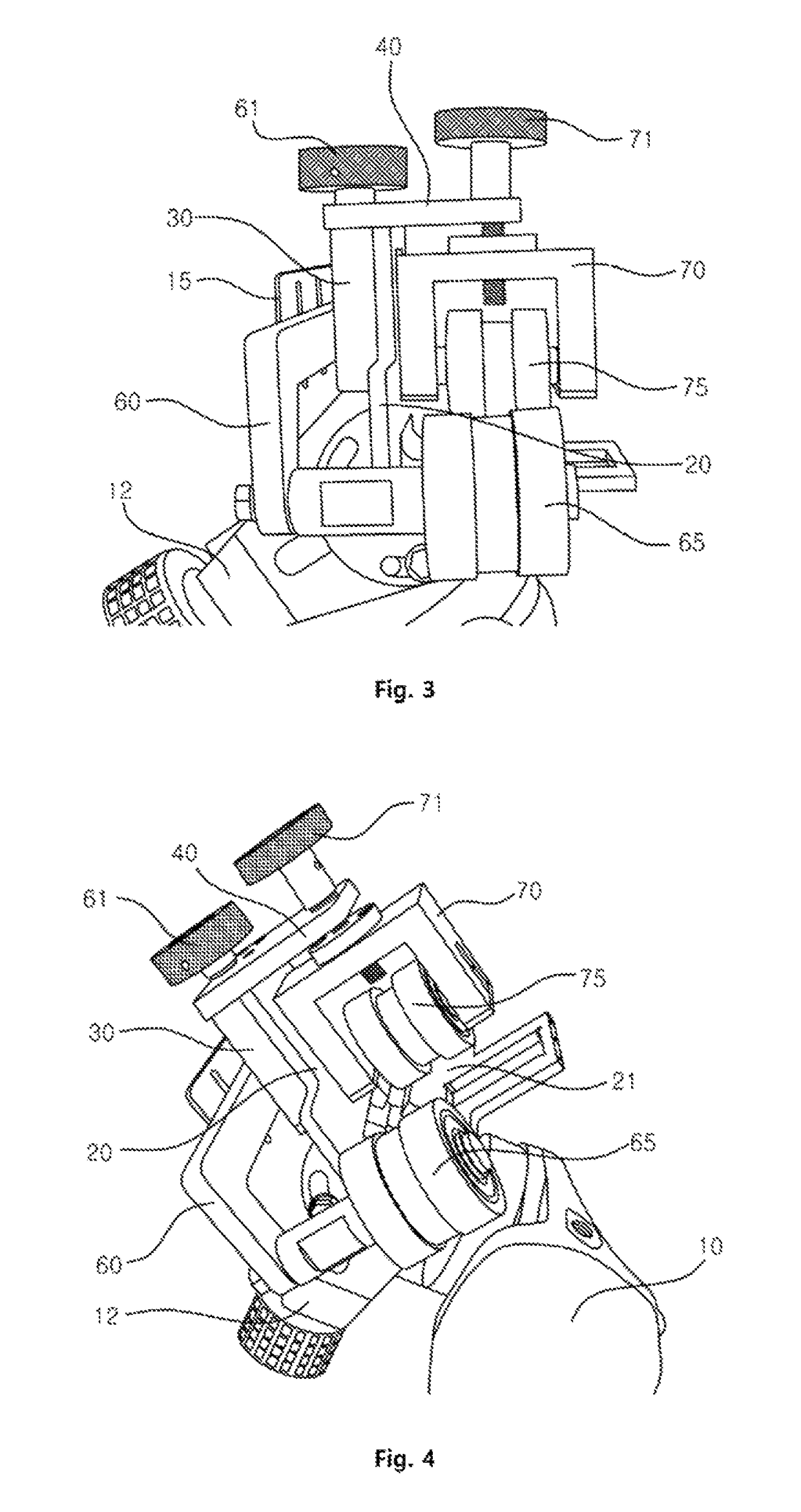
[0017]In the present invention, the circumscribing rollers and the inscribing roller rotate in only one direction by the use of one-way clutches, the inscribing roller maintains a state of being in close contact with the inside of the pipe due to the tension of the spring, and the circumscribing rollers may adjust the height and be closely adhered to the pipe regardless of the diameter of the pipe.
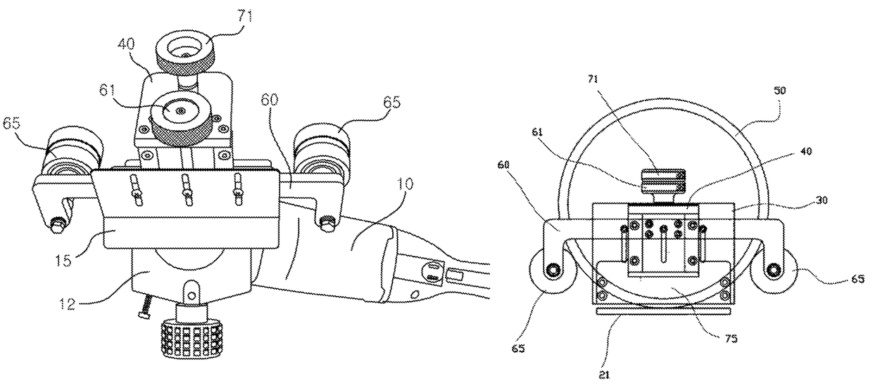
[0019]The present invention provides a pipe outer diameter-chamfering apparatus for chamfering the cutting surface of the pipe for welding, wherein the chamfering is performed by moving the circumscribing rollers up and down regardless of the pipe diameter and closely adhering them to the outside of the pipe. Thus, the chamfering of the pipe is performed elaborately, while the chamfering can be performed regardless of the diameter of the pipe. Further, the chamfering is performed in one direction and thus the chamfering work may be convenient and safe. Especially, due to the simple structure and convenient portability, it is possible to conveniently perform the chamfering of the pipe during plant piping work performed in elevated places.

Problems solved by technology

However, the chamfering work on the cutting surface of pipes in which pipes have been already installed in the course of performing the piping work is very difficult.
Therefore, the pipe chamfering work using a tool such as a portable grinder does not provide a regular chamfered angle and is performed while rotating grinder along the cutting surface of the pipes.
Therefore, the work is difficult and the work is performed at elevated places, the working environment thereby becomes poor.
Thus, the work of chamfering the cutting surface of the pipes during the plant work using a pipe chamfering apparatus may be difficult.
That is, when a grinder with a free rotation and angle adjustment is used for the chamfering work on the cutting surface of the pipes, a regular chamfered angle is not guaranteed and the worker has to perform the work while rotating the grinder along the outer diameter of the pipe one by one.
Therefore, the work efficiency decreases and the work may be dangerous.
Therefore, there are problems that several kinds of chamfering apparatuses must be provided in compliance with the diameter of the pipe, and such automatic chamfering apparatuses cannot be easily used to perform the work in elevated places.

Method used


Image

  • Portable pipe outer diameter-chamfering apparatus with improved weldability
  • Portable pipe outer diameter-chamfering apparatus with improved weldability
  • Portable pipe outer diameter-chamfering apparatus with improved weldability

Examples


Embodiment Construction

[0031]Hereinafter, the configuration and operation of preferred embodiments of the present invention will be described in detail with reference to the accompanying drawings. Here, in the case of assigning the reference numerals to the components of the drawings, it should be noted that, with respect to the same components, the same reference numerals are used even in different drawings.

[0032]The present invention relates to the use of a portable chamfering apparatus to a cutting surface of a pipe, wherein a vertical plate and a support plate are fixed in an orthogonal direction to a half-moon shaped chamfered angle adjustment plate fixed to either side of a head of the portable chamfering apparatus, and then the chamfering is performed by projecting a knife blade located between the vertical plate and the support plate. Herein, two circumscribing rollers are closely adhered to the outside of the pipe while one inscribing roller is closely adhered to the inside of the pipe, and the k...


PUM

PropertyMeasurementUnit
diameteraaaaaaaaaa
forceaaaaaaaaaa
elastic forceaaaaaaaaaa

Abstract

The present invention relates to a portable pipe outer diameter-chamfering apparatus characterized in that a vertical fixing plate is fixed to the outside of the vertical plate, a horizontal fixing plate is fixed in an orthogonal direction to the tip of the vertical fixing plate, a rectangular link with one open side is coupled to move upward and downward along the vertical fixing plate, a pair of circumscribing rollers, each of the pair of circumscribing rollers being installed on either end portion of the rectangular link with one open side, respectively, the rectangular link with one open side moves up and down along the vertical fixing plate, a moving body is installed in the horizontal fixing plate, the moving body moves up and down, and an inscribing roller which is in close contact with an inside of the pipe is installed on the moving body.

Description

CROSS-REFERENCE TO RELATED APPLICATION(S)[0001]This application claims the benefit of Korean Application No. 10-2015-0007489, filed on Jan. 15, 2015, with the Korean Intellectual Property Office, the disclosure of which is hereby incorporated by reference in its entirety.BACKGROUND[0002]1. Technical Field[0003]The present invention relates to a portable pipe outer diameter-chamfering apparatus with improved weldability which chamfers the edge of a pipe to weld a cutting pipe, and more particularly a portable pipe chamfering apparatus capable of easily chamfering pipes with various diameters in a simple structure.[0004]2. Description of the Related Art[0005]For the welding of pipes, the cutting surfaces of the pipes have to be chamfered. However, the work of chamfering a cutting pipe at the bottom is performed by engaging pipes with a conventional chamfering apparatus and thus the work can be easily performed. However, the chamfering work on the cutting surface of pipes in which pipe...

Claims


Application Information

Patent Timeline
Patent Type & Authority Patents(United States)
IPC IPC(8): B23B5/16
CPCB23B5/161B23B2215/72B23B2220/04B23B2260/116B23C3/122B23Q9/0028B23Q9/02B23B2260/136B23C3/126B23C2220/16B23C1/20
Inventor LEE, JONG IL
Owner LEE JONG IL
Learn More