Haptic throttle devices and methods

a technology of haptic throttle and throttle device, which is applied in the direction of electrical control, propulsion unit arrangement, vehicle components, etc., can solve the problems of known mechanical systems that reproduce and/or simulate the necessary friction, but are not ideal

Active Publication Date: 2006-08-29
IMMERSION CORPORATION
View PDF7 Cites 79 Cited by
  • Summary
  • Abstract
  • Description
  • Claims
  • Application Information

AI Technical Summary

Problems solved by technology

Known mechanical systems that reproduce and / or simulate the necessary friction, however, are not ideal due to variation in the friction output associated with various parameters including system component inconsistencies, mechanical wear of system components, and variation in operating environment (e.g., temperature, humidity, atmospheric pressure, etc.).

Method used


Image

  • Haptic throttle devices and methods
  • Haptic throttle devices and methods
  • Haptic throttle devices and methods

Examples


Embodiment Construction

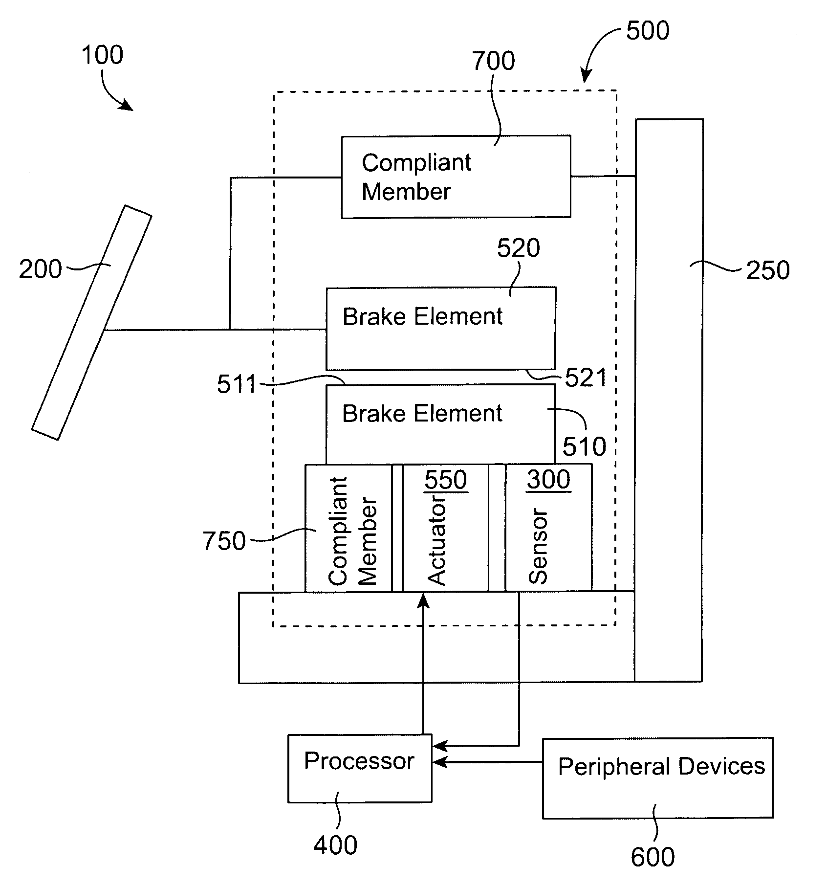
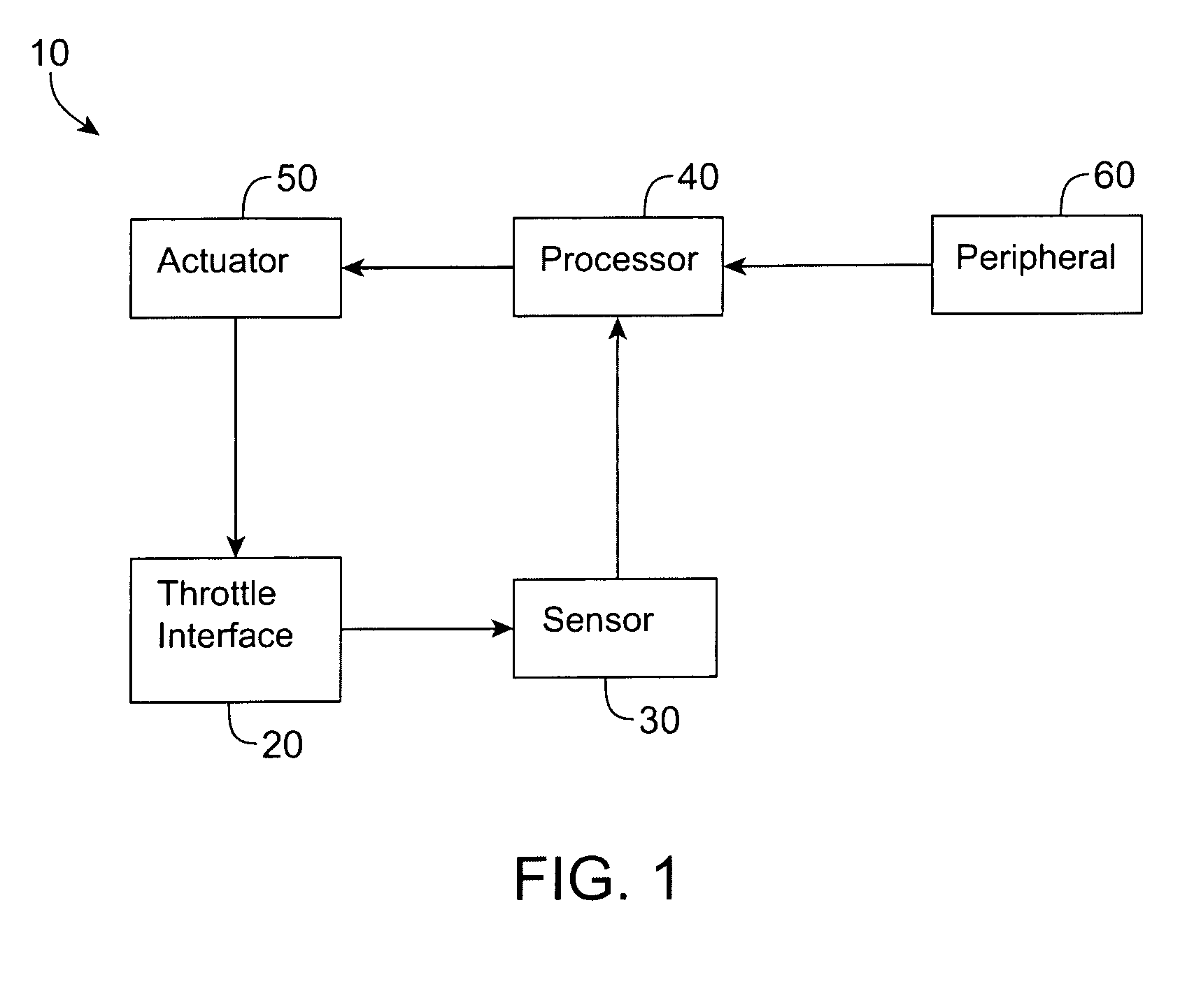
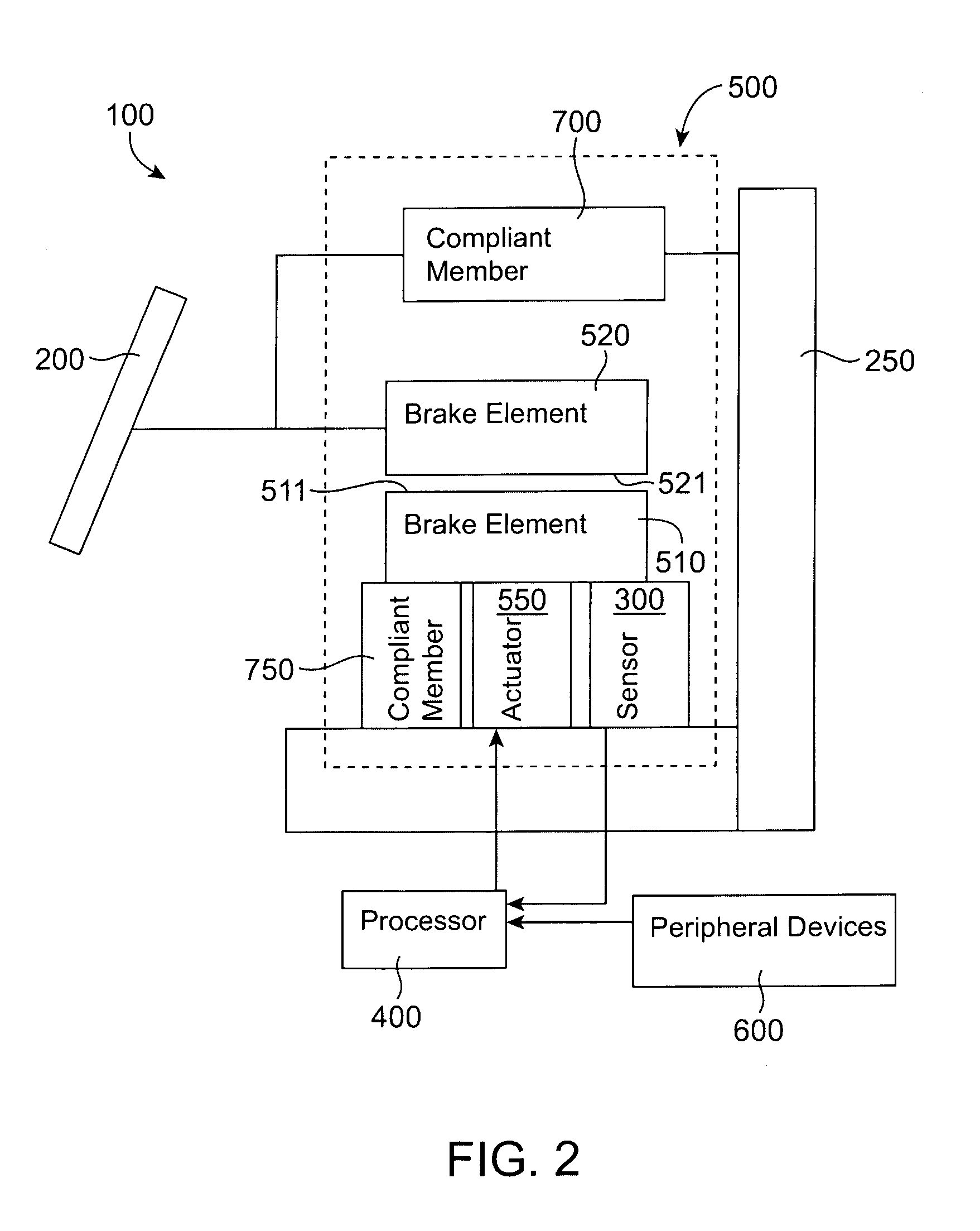
[0015]An apparatus is disclosed that includes a sensor configured to be coupled to a throttle interface. The sensor is configured to output a sensor signal associated with a condition of the throttle interface. A first brake element has a first friction surface, and a second brake element has a second friction surface. The second brake element is configured to be coupled to the throttle interface. The friction surface associated with the first brake element is positioned opposite the friction surface associated with the second brake element. The first brake element is configured to move relative to the second brake element. An actuator is coupled to the first brake element and is configured to output haptic feedback to the throttle interface via the first brake element based on the sensor signal.

[0016]In other embodiments, a method includes receiving a first input signal from a throttle interface and outputting a sensor signal associated with the input signal, the sensor signal bein...


PUM


Abstract

An apparatus includes a sensor configured to be coupled to a throttle interface. The sensor is configured to output a sensor signal associated with a condition of the throttle interface. A first brake element has a first friction surface and a second brake element has a second friction surface. The second brake element is configured to be coupled to the throttle interface. The friction surface associated with the first brake element is positioned opposite the friction surface associated with the second brake element. The first brake element is configured to move relative to the second brake element. An actuator is coupled to the first brake element and is configured to output haptic feedback to the throttle interface via the first brake element based on the sensor signal.

Description

CROSS-REFERENCE TO RELATED APPLICATION[0001]This application claims the benefit of U.S. Patent Application No. 60 / 516,187, entitled “Self-Regulating Resistive Actuator for Automotive Throttle Pedal Force Feedback,” filed on Oct. 30, 2003, the entirety of which is incorporated herein by reference.BACKGROUND[0002]The invention relates generally to haptic feedback systems, and more particularly, to a haptic feedback system associated with an automotive throttle actuator.[0003]Control of a vehicle through the use of electronically-controlled mechanisms rather than mechanically-controlled mechanisms has been implemented in different forms. Typically called “steer-by-wire,”“drive-by-wire,” or “control-by-wire,” electronically-controlled mechanisms direct electric motors and / or hydraulic or pneumatic control systems, to perform mechanical operations rather than a user directly performing the mechanical operations using a mechanical interface. For example, in a standard mechanical steering ...

Claims


Application Information

Patent Timeline
Patent Type & Authority Patents(United States)
IPC IPC(8): F02D11/10F02D41/26
CPCF02D11/105F02D41/26F02D2200/0404B60W50/16F02D2200/602B60K2026/023
Inventor GREGORIO, PEDRO
Owner IMMERSION CORPORATION
Why Eureka
Try Eureka