Double impingement vane platform cooling

a technology of impingement cooling and turbine vane platform, which is applied in the direction of liquid fuel engines, vessel construction, marine propulsion, etc., can solve the problems of complex construction, inability to adapt easily, and high manufacturing cost, and achieve the effect of improving the impingement cooling of the turbine vane platform

Active Publication Date: 2006-08-29
PRATT & WHITNEY CANADA CORP
View PDF18 Cites 43 Cited by
  • Summary
  • Abstract
  • Description
  • Claims
  • Application Information

AI Technical Summary

Benefits of technology

[0003]It is therefore an object of the present invention to do provide improved impingement cooling of a turbine vane platform.

Problems solved by technology

However, this construction is complex and expensive to manufacture, and not readily adaptable to variations in the impingement cooling characteristics.

Method used


Image

  • Double impingement vane platform cooling
  • Double impingement vane platform cooling
  • Double impingement vane platform cooling

Examples


Embodiment Construction

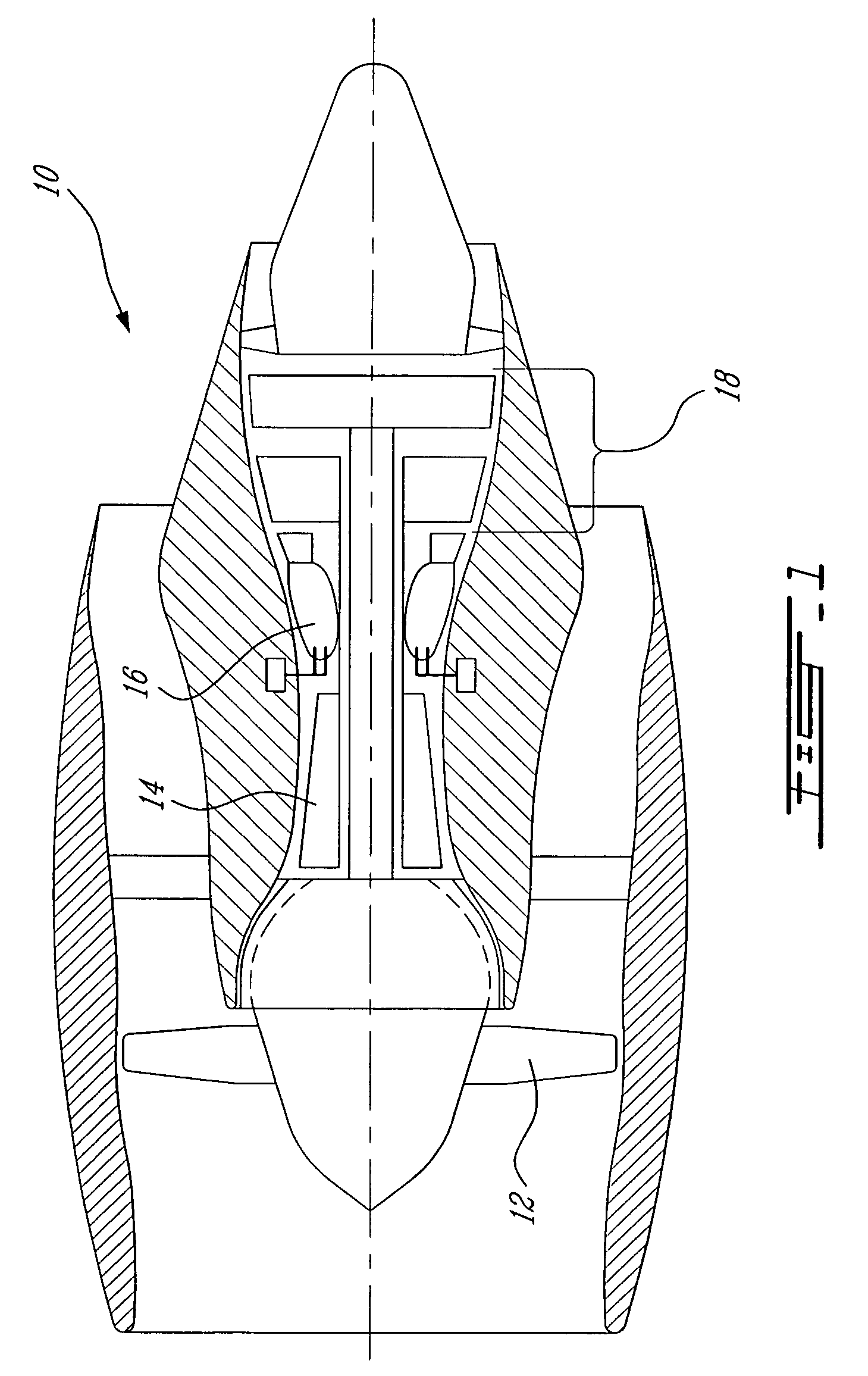
[0012]FIG. 1 illustrates a gas turbine engine 10 of a type preferably provided for use in subsonic flight, generally comprising in serial flow communication a fan 12 through which ambient air is propelled, a multistage compressor 14 for pressurizing the air, a combustor 16 in which the compressed air is mixed with fuel and ignited for generating an annular stream of hot combustion gases, and a turbine section 18 for extracting energy from the combustion gases.

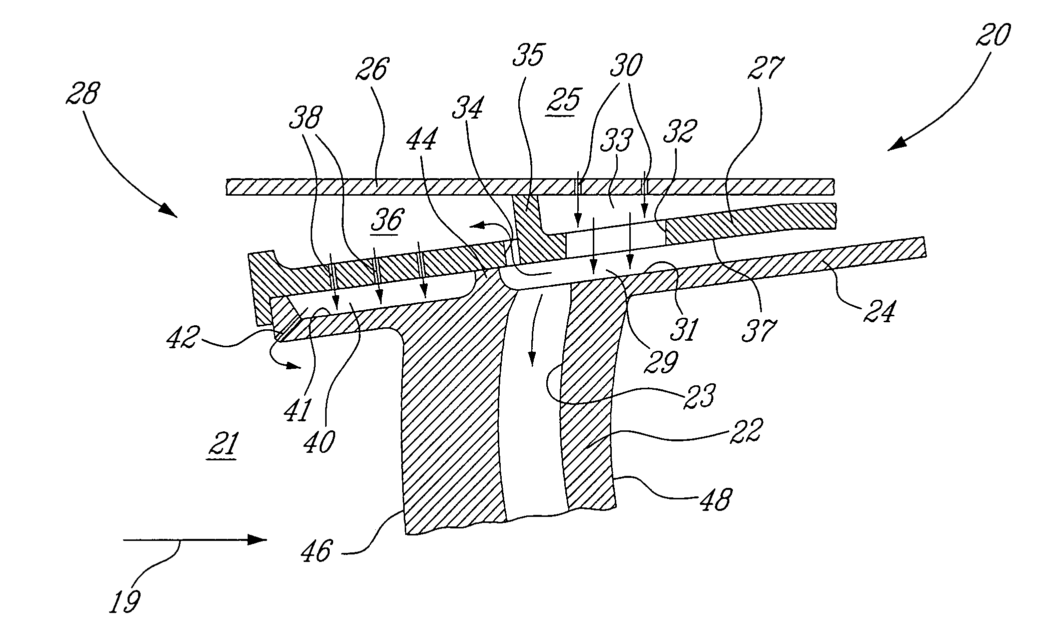
[0013]In order to derive improved benefit from the secondary cooling air bled from the primary gas flow, the vane assembly 20 of the present invention permits double impingement of the cooling air against a vane outer platform, and employs a structure which is simple and cost efficient to manufacture, and which permits flexibility in design such that the impingement cooling characteristics can be varied.

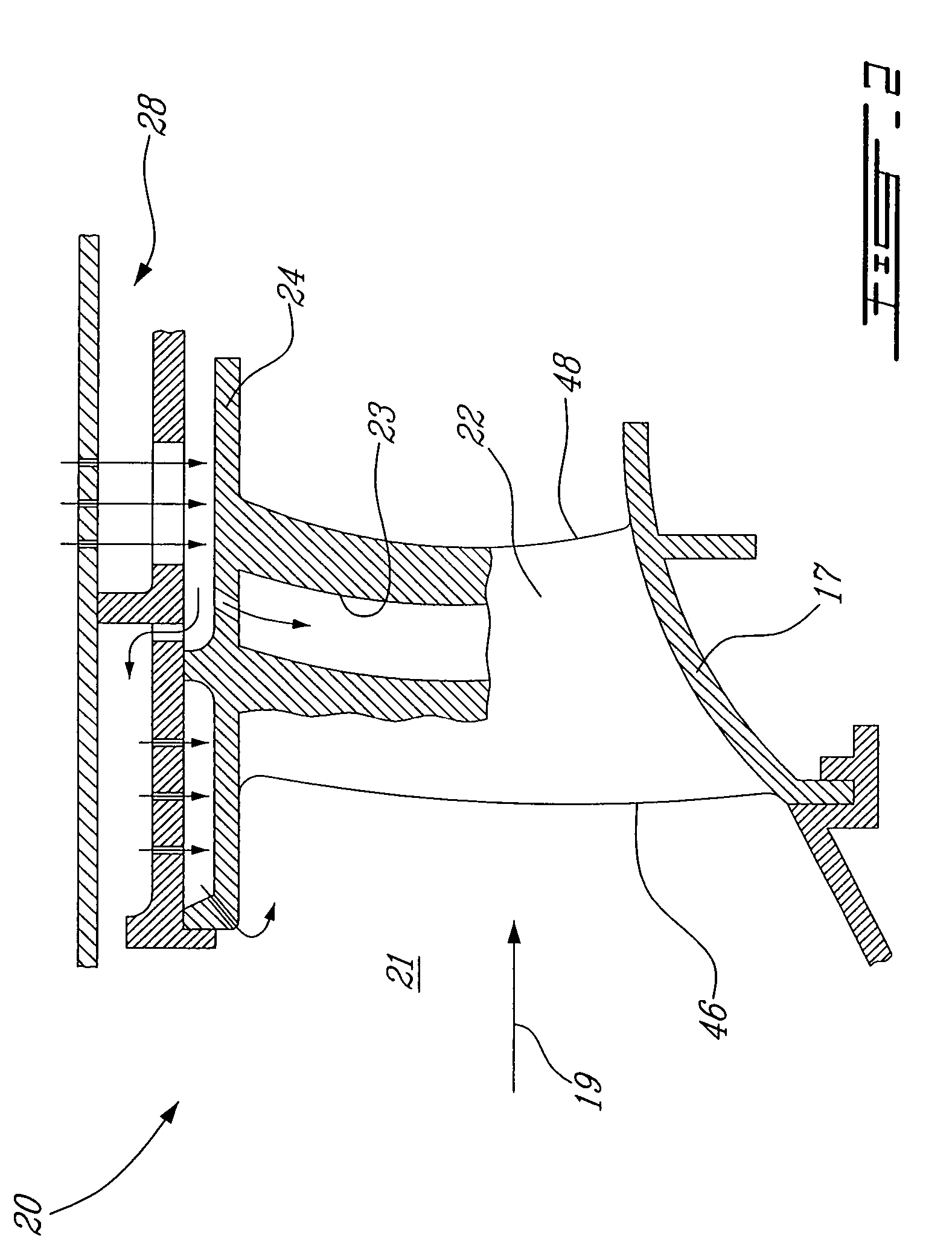
[0014]Referring to FIG. 2, the vane assembly 20 from the turbine section 18 of the gas turbine engine 10 includes an airfoil 2...


PUM


Abstract

A gas turbine engine vane assembly provides double impingement cooling of a vane platform. An impingement structure disposed adjacent the vane platform defines at least first and second plenums in fluid flow communication, respectively defined in part by the vane platform. The vane platform has first and second surfaces defined within the first and second plenums, and which are cooled by successive impingement of secondary cooling air flow through the impingement structure.

Description

TECHNICAL FIELD[0001]The invention relates generally to structure cooling in a gas turbine engine, and more particularly to impingement cooling of a turbine vane platform.BACKGROUND OF THE ART[0002]Turbine cooling is typically achieved using compressor bleed air. To improve cycle efficiency, it is desirable to reduce the amount of cooling air diverted form the main gas path. One approach is to use multiple-impingement, or re-use of cooling air to achieve additional cooling. For example, U.S. Pat. No. 4,573,865, to Hsia et al. discloses a multiple-impingement cooled turbine shroud having a unitary construction which includes impingement baffles and internal cavities within which a portion of the shroud surface is impinged with cooling air. However, this construction is complex and expensive to manufacture, and not readily adaptable to variations in the impingement cooling characteristics. Improvement is therefore desired.SUMMARY OF THE INVENTION[0003]It is therefore an object of the ...

Claims


Application Information

Patent Timeline
Patent Type & Authority Patents(United States)
IPC IPC(8): F03B11/02F01D1/00F01D5/18F01D5/22F01D25/14F02C7/18
CPCF01D5/18F01D9/041F05D2240/81Y02T50/60
Inventor TRINDADE, RICARDOPHAM, DAN QUELEBEL, LARRY
Owner PRATT & WHITNEY CANADA CORP
Why Eureka
Try Eureka