Coaxial connector with a substantially S-shaped switch

a coaxial connector and substantially s-shaped technology, applied in the direction of two-part coupling devices, electrical equipment, coupling device connections, etc., can solve the problems of poor connection between the switch terminals, poor coaxial connector thinness, poor connection between the switches, etc., and achieve the effect of thinning the coaxial connector

Inactive Publication Date: 2006-08-29
JST MFG CO LTD
View PDF14 Cites 9 Cited by
  • Summary
  • Abstract
  • Description
  • Claims
  • Application Information

AI Technical Summary

Benefits of technology

[0012]In the above-mentioned mode, the U-shaped section in the switch terminal is deformed in the direction crossing the direction of plug pin insertion. Therefore, it is possible to thin the coaxial connector while ensuring the elastic deformation range of the switch terminal.

Problems solved by technology

That is, the coaxial connector cannot be thinned.
Further, in a case where the plug pin 91 is too deeply pressed or a case where a foreign material such as a screw driver is inserted in place of the plug pin 91 so that the S like shape switch terminal 95 is excessively bent, the switch terminal 95 is plastically deformed, which may substantially result in a poor connection between the switch terminal 95 and the fixed terminal 94 after that.
When the dust is attached, as described above, therefore, the connection therebetween becomes poor.
Consequently, the coaxial connector may not be satisfactorily examined.

Method used


Image

  • Coaxial connector with a substantially S-shaped switch
  • Coaxial connector with a substantially S-shaped switch
  • Coaxial connector with a substantially S-shaped switch

Examples


Embodiment Construction

[0025]An embodiment of the present invention will be described while referring to the accompanying drawings.

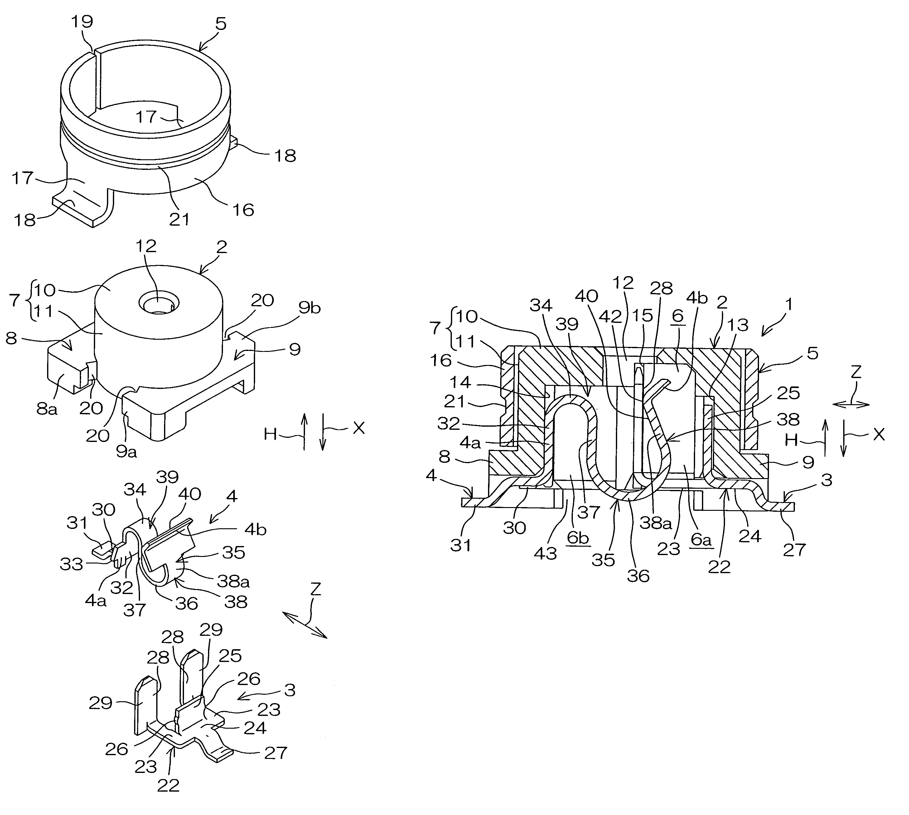
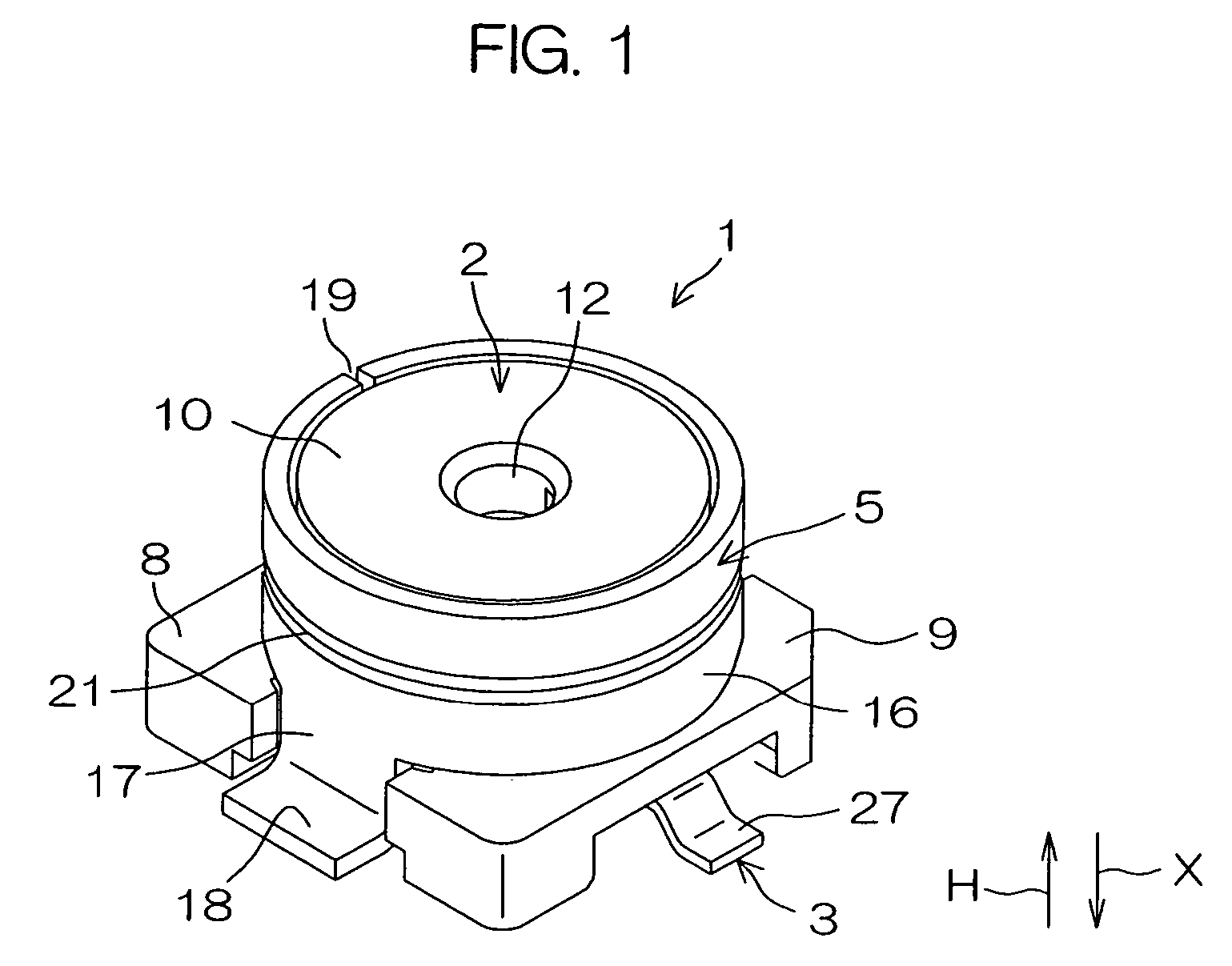
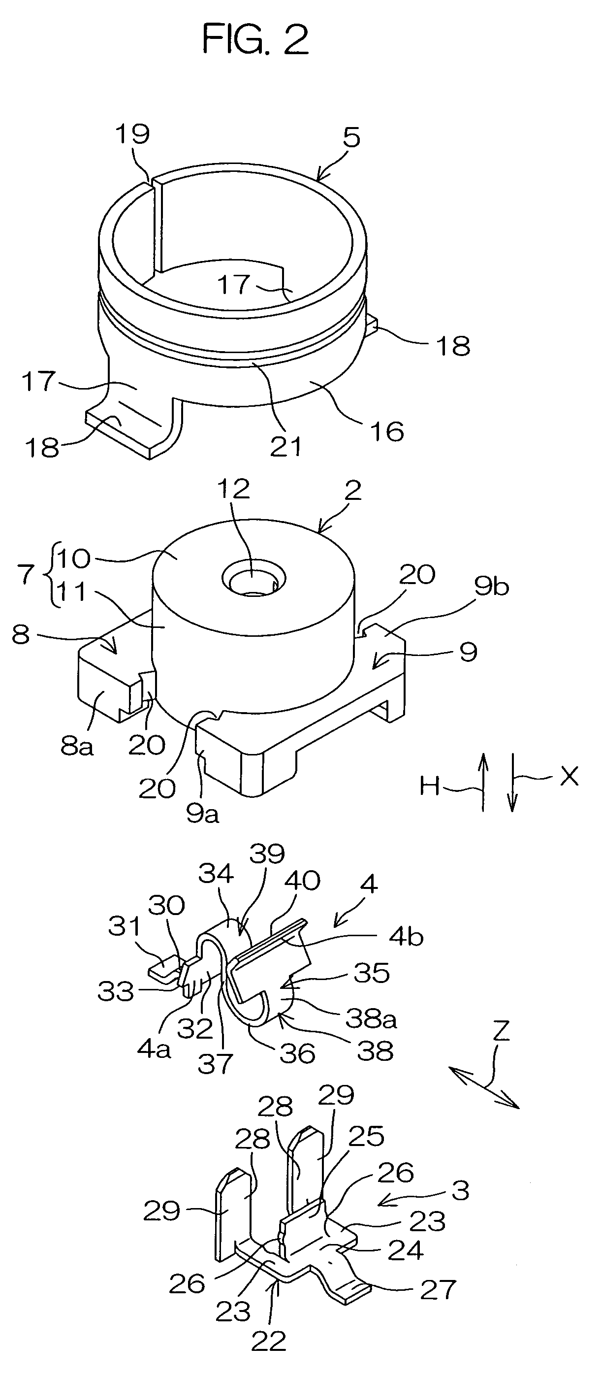
[0026]Referring to FIGS. 1 to 4, a coaxial connector with a switch 1 (hereinafter merely referred to as a connector 1) according to an embodiment of the present invention comprises a housing 2 composed of an insulative synthetic resin, a fixed terminal 3 and a switch terminal 4 which are held in the housing 2, and a shell for electromagnetic shielding 5 composed of a conductive metal having a cylindrical shape, surrounding the housing 2.

[0027]The housing 2 comprises a cylinder 7 for defining a terminal accommodation chamber 6 (see FIG. 5) in its inner part, and a pair of bases 8 and 9 provided in an extended manner sideward from the bottom of the cylinder 7. The cylinder 7 comprises an upper surface 10 and a peripheral side wall 11. At the center of the upper surface 10, a plug pin insertion hole 12 for inserting a plug pin 51 in an examination device 50 as shown in FIG. 11 in...


PUM


Abstract

A connector with a switch comprises a housing for defining a terminal accommodation chamber opened through a plug pin insertion hole. A fixed terminal and a switch terminal are held by the housing. The switch terminal comprises a U-shaped section opened toward the plug pin insertion hole in the terminal accommodation chamber. The U-shaped section is elastically deformable in a direction crossing the direction of plug pin insertion. The switch terminal is switched from a state in which it is brought into contact with the fixed terminal to a state in which the contact thereof with the fixed terminal is cut off as the U-shaped section is deformed in the direction crossing the direction of plug pin insertion.

Description

BACKGROUND OF THE INVENTION[0001]1. Field of the Invention[0002]The present invention relates to a coaxial connector with a switch which is connected to a transmission / receiving circuit in a radio terminal such as a cellular phone, a PHS (Personal Handyphone System), a radio LAN (Local Area Network) module, or an ETC (Electronic Toll Collection) module, and relates to the structure of a coaxial connector with a switch in which a connection of a switch terminal is switched from a fixed terminal to a plug pin by connection to a plug pin in a counterpart connector.[0003]2. Description of Related Arts[0004]Although a coaxial connector with a switch of this type generally connects a built-in transmission / receiving circuit and an attached antenna in a cellular phone, a PHS, or the like, for example, the connection between the built-in transmission / receiving circuit and the attached antenna is interrupted at the time of final examination before shipment to connect the built-in transmission...

Claims


Application Information

Patent Timeline
Patent Type & Authority Patents(United States)
IPC IPC(8): H01R29/00H01R13/707H01R13/70H01R103/00
CPCH01R24/46H01R24/50Y10S439/944H01R2201/06H01R2103/00H01R2201/16H01R13/70
Inventor FUKUZAKI, HIROSHIKASAMARU, YOICHI
Owner JST MFG CO LTD
Why Eureka
Try Eureka