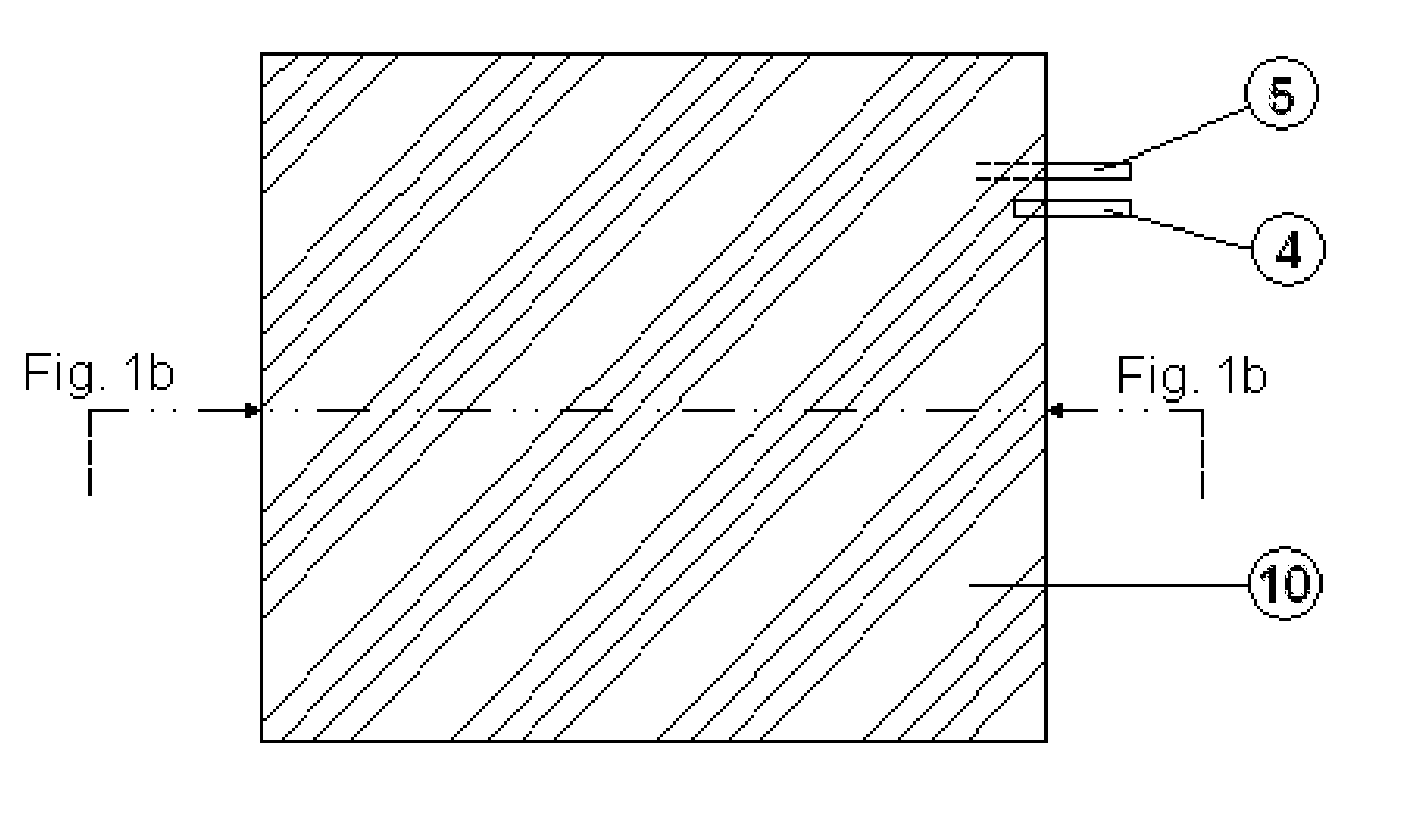
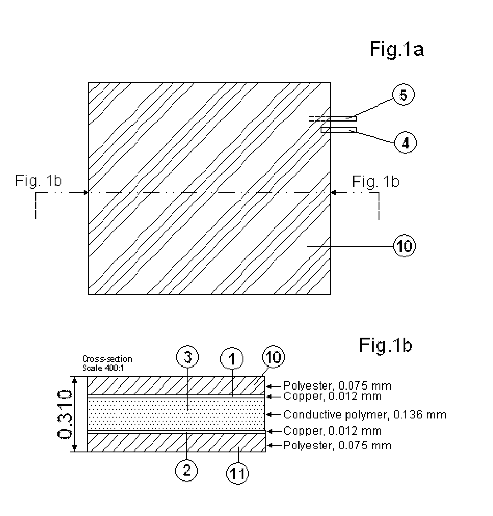
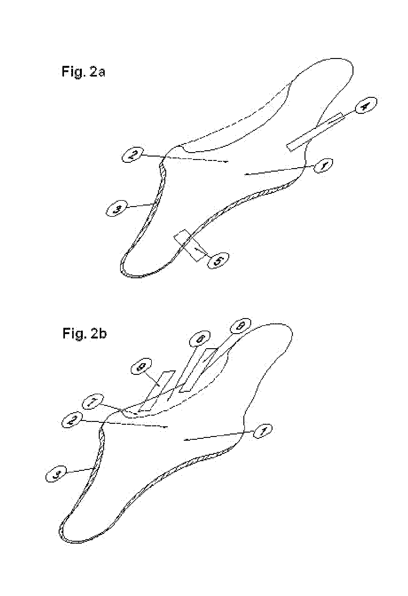
Heating element

Active Publication Date: 2010-12-23
CONFLUX
View PDF8 Cites 8 Cited by
  • Summary
  • Abstract
  • Description
  • Claims
  • Application Information

AI Technical Summary

Benefits of technology

[0013]A further object is to achieve a very thin heatin

Problems solved by technology

A problem with both this heating element and earlier such elements based on electrically conductive wires threaded through an electrically conductive body is that a small physical damage in the element, such as a hole, will shut off the electrical current and thereby the function

Method used


Image

  • Heating element
  • Heating element
  • Heating element

Examples


example 1

[0068]The following polymer compound material was prepared, the percentages being based on the weight of the complete composition:

1. PDMS46.5%2. CB MT (CTC powder)41.2%3. CB FEF (PTC powder)5.2%4. Silica7.2%

[0069]Further 0.36% by weight of the coupling agent based on the weight of the PTC powder.

[0070]The silica is a necessary filler to rheologically stabilize the matrix and increase the distance between carbon particles.

[0071]The powder fractions are sieved, the liquid coupling agent is added and the mixture is ultrasonically treated. All components are compounded to a stiff material that is laminated between copper foils. The laminate is heat treated at approximately 130° C. for

[0072]24 hours, where after curing is performed by irradiation with electron-beams into the compounded material, through the metal foils. The obtained silicone matrix is nearly completely crosslinked to form one sole molecule.

[0073]The obtained material has a trip temperature of about 45° C.

[0074]A multi-la...

example 2

[0076]The following polymer compound material was prepared, the percentages being based on the weight of the complete composition:

1. PDMS43.2%2. CB MT (CTC powder)50.0%3. CB FEF (PTC powder)4.5%4. Silica2.4%

[0077]Further 0.36% by weight of the coupling agent based on the weight of the PTC powder.

[0078]The PTC SIP compound was prepared in the same way as in example 1.

[0079]The obtained composite body has a trip temperature of about 40° C.

[0080]A multi-layered ZPZ foil structure comprising a 0.074 mm thick layer of PTC SIP compound present in between two copper foils of a thickness of 0.012 mm was connected to a power source supplying an AC or DC voltage of 12 V via two electrode strips on the copper foils. The layered structure was cooled to a temperature of −15° C. before switching on the power. The temperature rose to 5° C. within 30 seconds. The maximum equilibrium temperature was 35° C.

[0081]The trip temperature and maximum equilibrium temperature may be adjusted by changing 1) t...


PUM

PropertyMeasurementUnit
Temperatureaaaaaaaaaa

Abstract

A PTC SIP compound comprising an electrically insulating matrix essentially consisting of a siloxane polymer in addition to first and second electrically conductive particles having different properties with respect to surface energies and electrical conductivities. A multi-layered, ZPZ, foil comprising a PTC SIP compound of the invention present between two metal foils, thereby forming a conductive composite body. A multi-layered device, comprising an essentially flat composite body made up from a PTC SIP compound according to the invention, two electrode layers adhering to the surfaces of the composite body, the electrode layers being metal foils prepared to connect to electrodes.

Description

FIELD OF THE INVENTION[0001]A positive temperature coefficient, PTC, superimposed impedance polymeric, SIP, compound, a multi-layered, zero-positive-zero temperature coefficient, ZPZ, foil and a multi-layered device comprising a multi-layered ZPZ foil comprising a PTC SIP compound.BACKGROUND OF THE INVENTION[0002]Several types of self limiting electrical heating elements are known from, e.g., German patent No. 2,543,314 and the corresponding U.S. Pat. Nos. 4,177,376, 4,330,703, 4,543,474, and 4,654,511.[0003]Further, U.S. Pat. No. 5,057,674 describes such an element comprising two outer semiconductive layers allegedly having a zero temperature coefficient (“ZTC”) separated from one another by a continuous positive temperature coefficient (“PTC”) layer and energized by two parallel electrodes, the first one being in contact with one end of one of the ZTC layers and the second parallel electrode being in contact with the other ZTC layer at its end furthest removed from the first elect...

Claims


Application Information

Patent Timeline
IPC IPC(8): H05B3/14
CPCH05B3/28H05B2203/02H01C7/06H01C17/0652Y10T29/49082H01C7/027H05B3/145H05B3/146Y10T29/49085H01C17/06586H05B3/14
Inventor VON WACHENFELDT, FREDRIKMORTENSON, PER -GORAN MIKAELNYBERG, GUNNARNILSSON, LARS-OVESJOSTRAND, JOACHIM
Owner CONFLUX
Why Eureka
Try Eureka