
Multi-mode oil base mud imager

a multi-mode, oil-based mud technology, applied in the direction of instruments, measurement devices, scientific instruments, etc., can solve the problems of no resistivity measurement, many wells in the gulf of mexico and the north sea cannot be drilled economically, and many known micro-resistivity tools in these non-conductive oil-based mud systems were seriously degraded

Active Publication Date: 2006-08-29
HALLIBURTON ENERGY SERVICES INC
View PDF7 Cites 69 Cited by
  • Summary
  • Abstract
  • Description
  • Claims
  • Application Information

AI Technical Summary

Benefits of technology

The patent text describes a technique for measuring the properties of the earth formation during drilling of a well. This is commonly known as "logging while drilling" or "MWD". The text explains that during drilling, a probe or "sonde" is lowered into the borehole to measure various parameters and conditions downhole. The sonde is pulled uphole using a cable or wireline, which provides mechanical support and also acts as an electrical conductor to transmit information signals. The text also describes the use of resistivity tools to measure the resistivity of the formation, which is indicative of the presence of oil or gas. However, in non-conductive oil-based muds, the high resistance of the mud prevents the flow of current and thus affects the performance of the resistivity tools. The patent text proposes a solution to this problem by using a resistivity tool against the borehole wall, but this requires an imperfect contact or a high-resistance mud cake, which can lead to inaccurate measurements. The patent text proposes a new technique to address this problem and provide more reliable and accurate resistivity measurements in non-conductive muds.

Problems solved by technology

For example, many wells in locations such as the Gulf of Mexico and the North Sea cannot be drilled as economically using water-based mud technology because of wellbore stability problems.
Performance of many known micro-resistivity tools in these non-conductive oil-based mud systems was seriously degraded.
Without a flow of current, no resistivity measurement can be made and thus measurements from a current emitting resistivity tool were rendered either useless or much less reliable.
It was thought that the advantages of microresistivity borehole imagers to collect information regarding the borehole might be lost when using non-conductive drilling fluids.

Method used


Image

  • Multi-mode oil base mud imager
  • Multi-mode oil base mud imager
  • Multi-mode oil base mud imager

Examples


Embodiment Construction

[0041]A multi-mode oil base mud imager and related methods are disclosed. The invention, however, has a number of different aspects, each of which has features that may be separately patentable.

[0042]The invention takes advantage of the natural defocusing of a current flow as it travels from a source to a sink. FIG. 6A uses a point source model to describe a principle underlying embodiments of the invention. N is a current source, P is a current return and M is a monitor electrode. A set of current lines 610 depict current as it travels directly from current source N to current return P. Current line 620 shows the current as it travels from current source N to current return P but as detected from monitor electrode M. Current travels along line 620 from current source N to current return P regardless whether monitor electrode M is present but without the presence of monitor electrode M, the characteristics of current line 620 are not detected.

[0043]At an intersection of each current...


PUM


Abstract

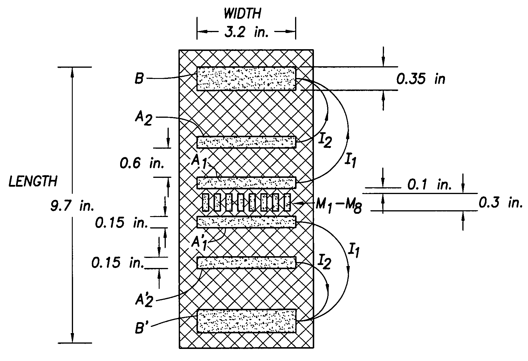
A multi-mode oil base mud imager for use in non-conductive drilling fluid includes at least one current source—a current return pair, and one or more monitor electrodes not located between the current source and the current return of the current source-current return pair. Where more than one current source-current return pair is included, the tool is capable of multiple depths of investigation into surrounding formation. This data can be used as a gauge to establish the reliability of the data and to determine the resistance of the invaded zone around the borehole, as well as standoff distance of the tool from the borehole wall.

Description

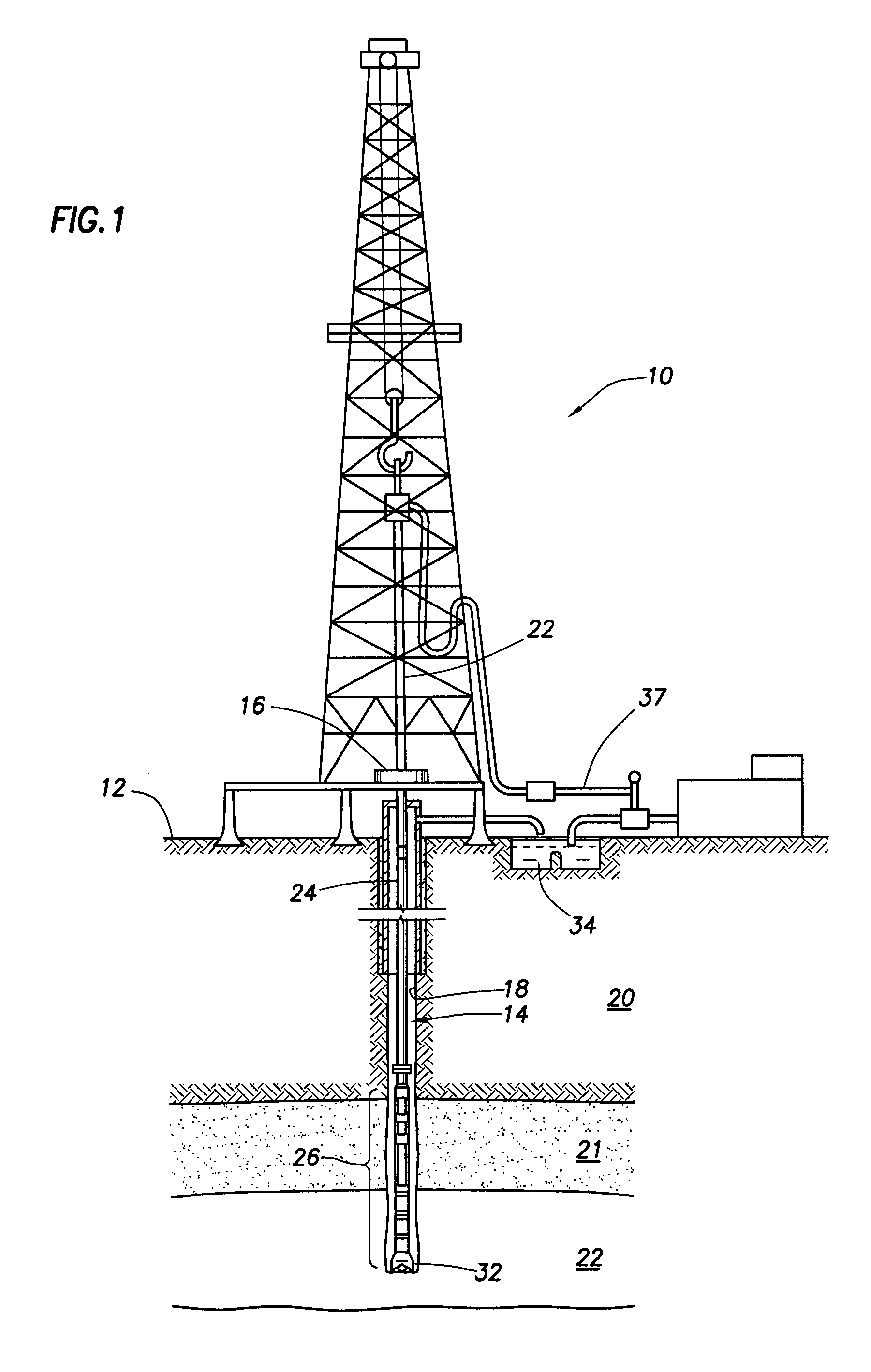
CROSS-REFERENCE TO RELATED APPLICATIONS[0001]Not Applicable.STATEMENT REGARDING FEDERALLY SPONSORED RESEARCH OR DEVELOPMENT[0002]Not Applicable.BACKGROUND OF THE INVENTION[0003]In drilling a borehole in the earth, such as for the recovery of hydrocarbons or for other applications, it is conventional practice to connect a drill bit on the lower end of an assembly of drill pipe sections which are connected end-to-end so as to form a “drill string.”FIG. 1 includes a drilling installation having a drilling rig 10 at the surface 12 of a well, supporting a drill string 14. The drill string includes a bottom hole assembly 26 (commonly referred to as a “BHA”) coupled to the lower end of the drill string 14. The BHA includes the drill bit 32, which rotates to drill the borehole. As the drill bit 32 operates, drilling fluid or mud is pumped from a mud pit 34 at the surface into the drill pipe 24 and to the drill bit 32. After flowing through the drill bit 32, the drilling mud rises back to th...

Claims


Application Information

Patent Timeline
Patent Type & Authority Patents(United States)
IPC IPC(8): G01V3/20G01V3/24
CPCG01V3/24
Inventor BITTAR, MICHAEL S.HU, GUOYU DAVIDBUCHANAN, JAMES
Owner HALLIBURTON ENERGY SERVICES INC
Learn More