Power line communication system and method of operating the same

a power line and communication system technology, applied in the field of data communication, can solve the problems of limiting many challenges to overcome, and the power line is not designed to provide high-speed data communication, so as to achieve the effect of reducing the strength of the data signal that can be injected onto the power line, and reducing the risk of interferen

Inactive Publication Date: 2006-08-29
CURRENT TECH
View PDF53 Cites 276 Cited by
  • Summary
  • Abstract
  • Description
  • Claims
  • Application Information

AI Technical Summary

Problems solved by technology

While the concept may sound simple, there are many challenges to overcome in order to use power lines for data communication.
Power lines are not designed to provide high speed data communications and are very susceptible to interference.
Additionally, federal regulations limit the amount of radiated energy of a power line communication system, which therefore limits the strength of the data signal that can be injected onto power lines (especially overhead power lines).
Power system transformers are another obstacle to using power distribution lines for data communication.
As such, some power line communications systems face the challenge of communicating the data signals around, or through, the distribution transformers.
However, the cost of installing the conventional communications medium (i.e., non-power line communications medium) may be very significant and in some instances, prohibitive from a business perspective.
In particular, a major cost of installing such media is the segment that extends from the common communication link, which typically is along the street, to each customer premises.

Method used


Image

  • Power line communication system and method of operating the same
  • Power line communication system and method of operating the same
  • Power line communication system and method of operating the same

Examples


example embodiments

Overview of Example Embodiments

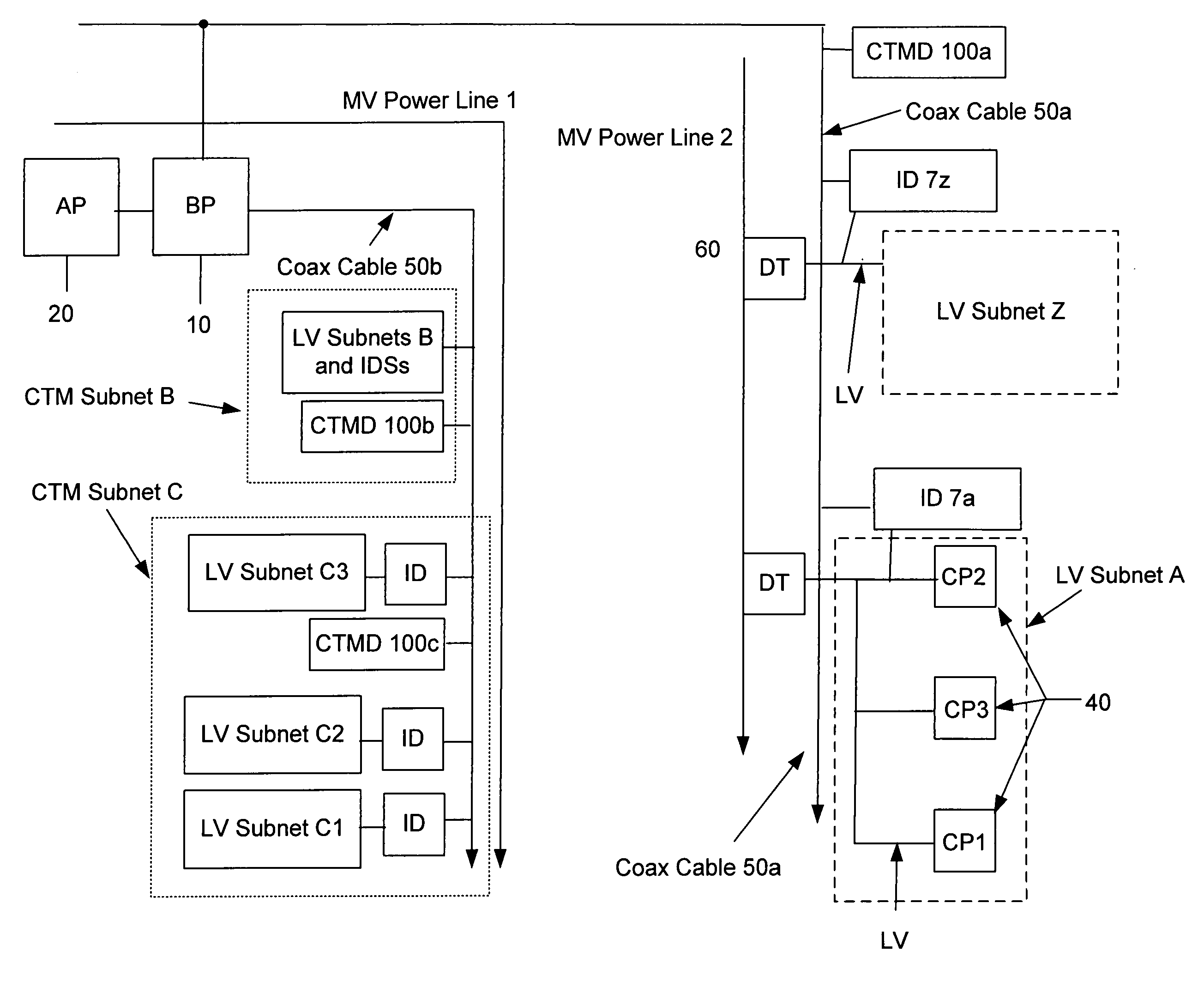
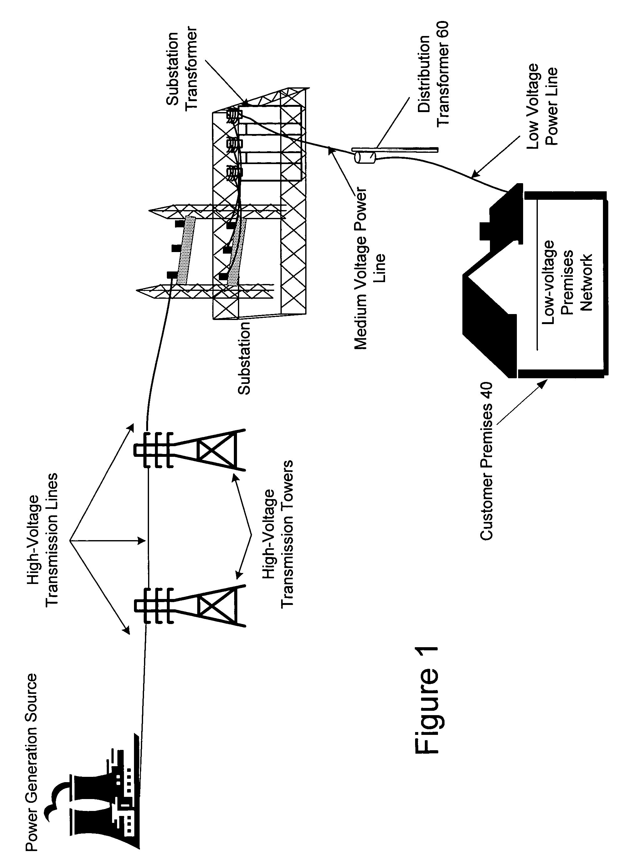
[0027]The present invention employs the LV power lines, including the internal and external LV power lines associated with customer premises, and a conventional telecommunications medium (CTM) (i.e., a non-power line communications medium). Some embodiments also may employ the MV power lines. In addition, the invention may be used with overhead or underground power distribution systems.

[0028]Specifically, a power line modem, such as a HomePlug™ compliant modem (e.g., HomePlug 1.0 or HomePlug AV standard), interfaces the user device (such as computer, telephone, fax, etc.) to the internal LV wiring of the customer premises. The power line modem may be a stand alone device or integrated into the user device.

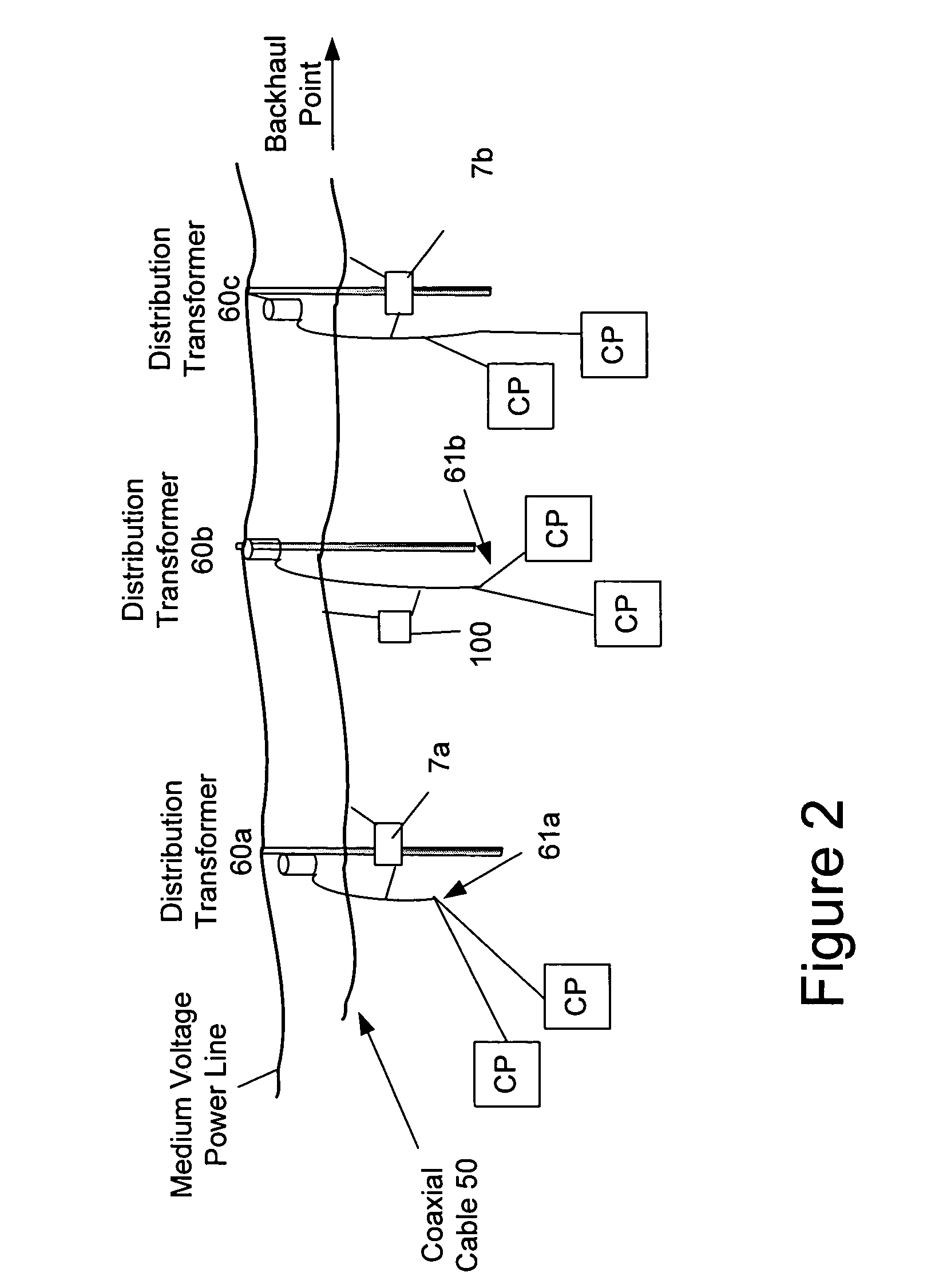
[0029]The power line modem couples the data from the user device to the internal LV power lines. The data propagates from the internal to the external LV power lines until reaching an interface device such as power line-coaxial interface device (PLCID...


PUM


Abstract

The present invention provides a power line communications system that may employ power lines and non-power communications mediums. In one embodiment, the system is comprised of a plurality of interface devices with each being in communication with one or more user devices via one or more low voltage power lines. Each interface device also may be in communication with an upstream communications device via a non-power line communications medium. The upstream communications device may communicate with a backhaul point via a backhaul link to provide access to a network such as the Internet. In one embodiment, each interface device provides an interface between one or more low voltage power lines and the non-power line communications medium, which may be a coaxial cable. The upstream communications device may provide routing for data communicated with the interface devices.

Description

CROSS REFERENCE TO RELATED APPLICATIONS[0001]This application claims priority under 35 U.S.C. § 119(e) to U.S. Provisional Patent Application Ser. No. 60 / 484,856 filed Jul. 3, 2003, which is incorporated herein by reference in its entirety.FIELD OF THE INVENTION[0002]The present invention generally relates to data communications over a power distribution system and more particularly, to a system and method for communicating data, which may include video, audio, voice, and / or other data types.BACKGROUND OF THE INVENTION[0003]Well-established power distribution systems exist throughout most of the United States, and other countries, which provide power to customers via power lines. With some modification, the infrastructure of the existing power distribution systems can be used to provide data communication in addition to power delivery, thereby forming a power line communication system (PLCS). In other words, existing power lines, that already have been run to many homes and offices,...

Claims


Application Information

Patent Timeline
Patent Type & Authority Patents(United States)
IPC IPC(8): H04M11/04H01P5/12H02J3/02H03H5/00H04BH04B3/56
CPCH04B3/56H04B2203/5483
Inventor BERKMAN, WILLIAM H.
Owner CURRENT TECH
Why Eureka
Try Eureka