
System and method for determining service requirements of network elements

Inactive Publication Date: 2006-08-29
BELLSOUTH INTPROP COR
View PDF9 Cites 132 Cited by
  • Summary
  • Abstract
  • Description
  • Claims
  • Application Information

AI Technical Summary

Benefits of technology

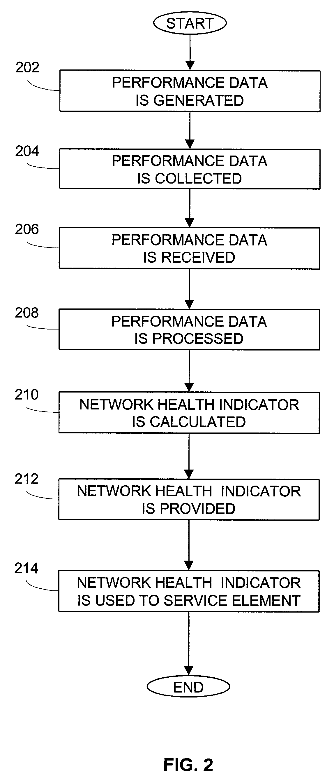
[0017]The network health indicator can also be used as an automated work driver for the NRC of the telephone network, providing a focused maintenance tool to the NRC. In conjunction with the Integrated NRC Tool System (INTS) ticketing system, the network health indicator can generate trouble tickets and exception reports to the NRC technicians. These trouble tickets and reports are prioritized and based on the network health indicator of the network elements. This allows for the work to be prioritized based on the network health indicator for the network element. Using network health indicator as a work driver provides the advantage to the NRC that the network elements performing the worst, per the network health indicator, will be addressed first by the maintenance personnel.

Problems solved by technology

In a network that has a large number of elements, it can be difficult to determine which element or elements require service.
For example, in a telephone network that has thousands of switches and other network elements, it is difficult to determine which of the network elements require maintenance to keep the element functioning within design tolerances.
Furthermore, it can be nearly impossible to prioritize which switches need service more urgently than the other switches.
Many users discontinued the use of the product because it was not user friendly.
Currently, NSPMP simply does not have the capability to monitor the performance of a majority of the switches that are being used in telephone networks, due to increased sophistication and complexity of the switches.

Method used


Image

  • System and method for determining service requirements of network elements
  • System and method for determining service requirements of network elements
  • System and method for determining service requirements of network elements

Examples


Embodiment Construction

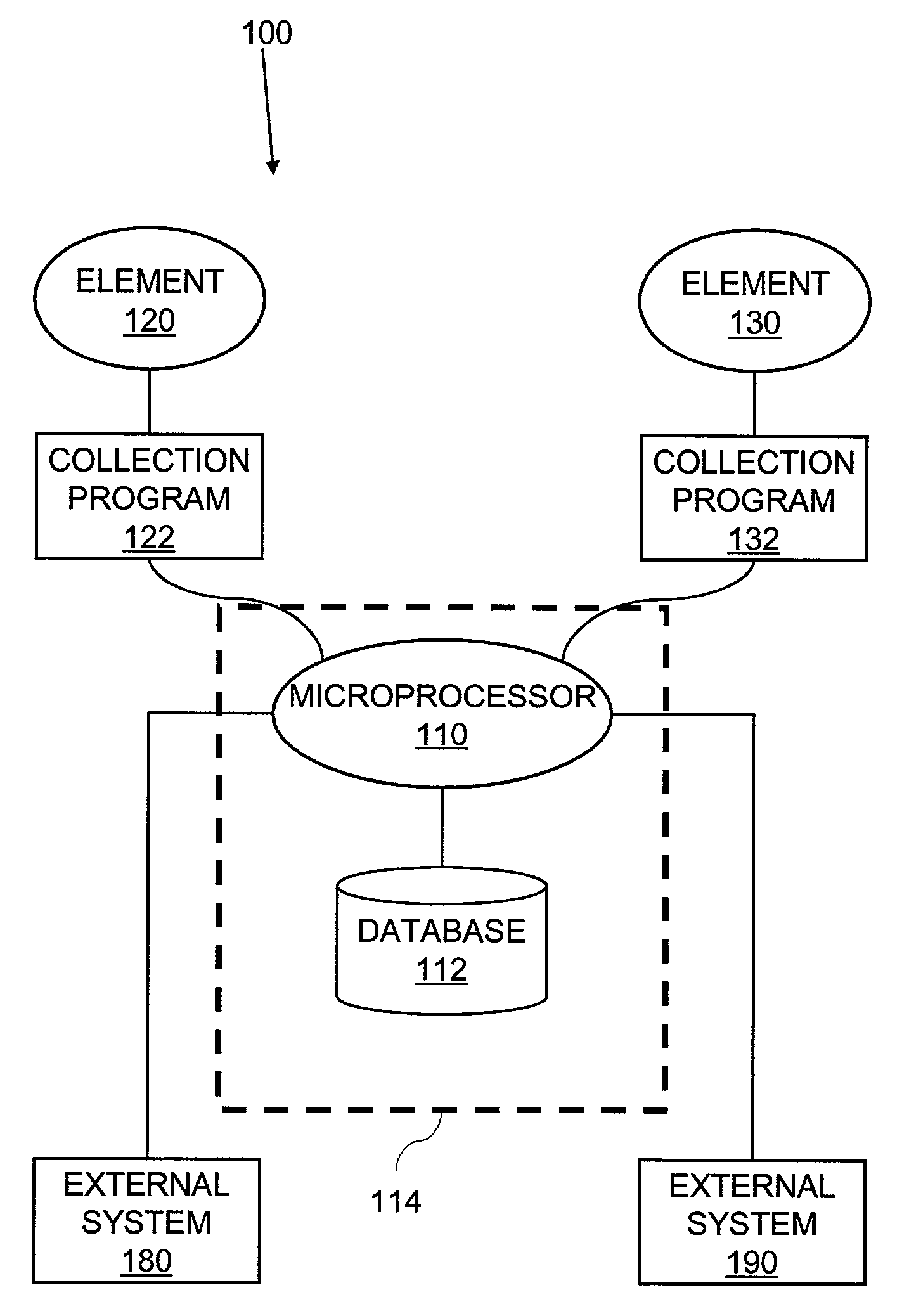
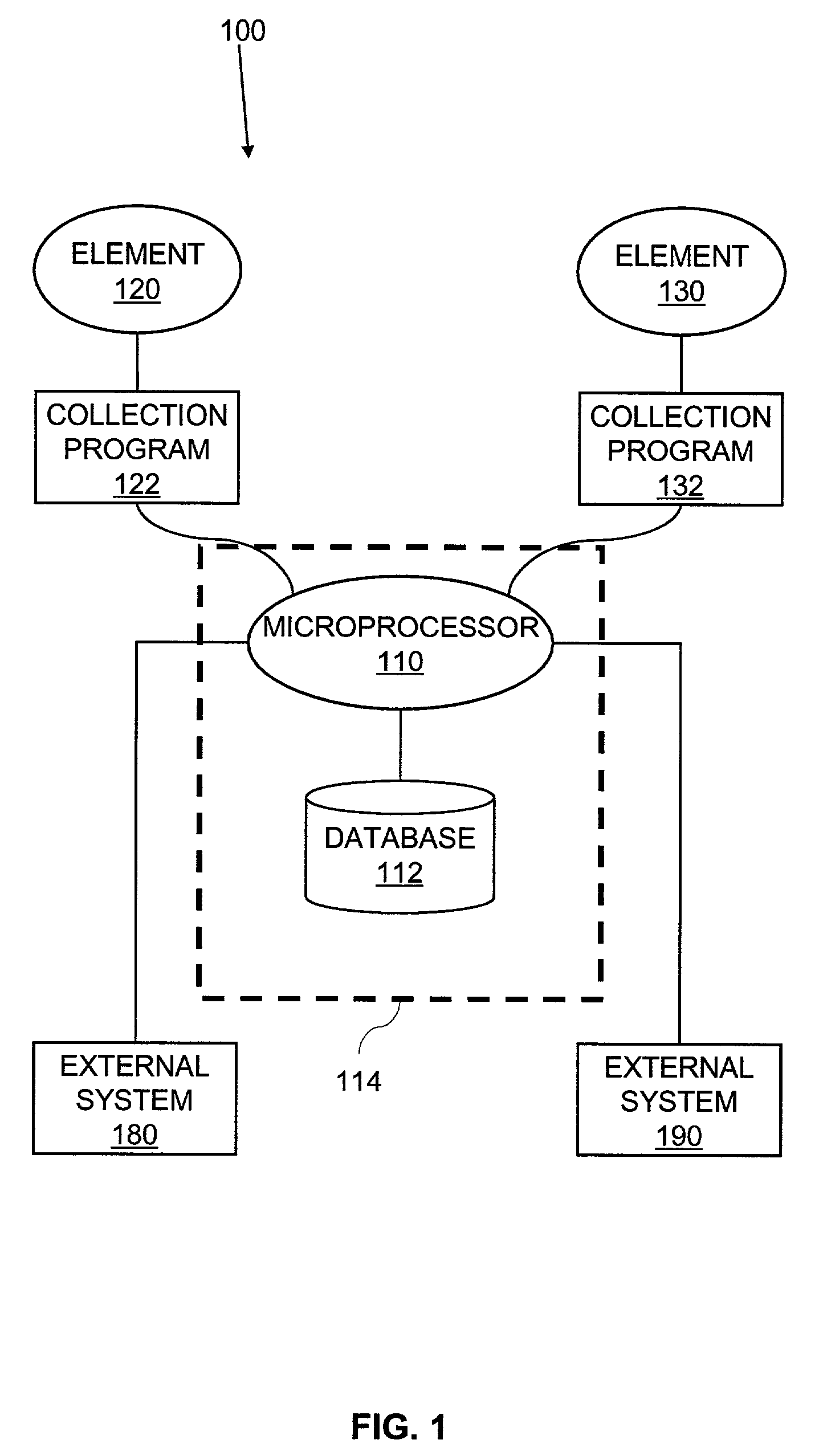
[0022]FIG. 1 is a schematic diagram showing a system architecture of an exemplary implementation of an embodiment of the invention. Network 100 has many elements, which include elements 120 and 130. It must be understood that network elements 120 and 130 are representative of a much larger number of network elements that make up network 100. Microprocessor 110 is in communication with each of the network elements, including elements 120 and 130. Database 112 is accessible by microprocessor 110. Preferably, both microprocessor 110 and database 112 are part of the same host computer 114 that is adapted to implement the present invention. However, database 112 may be stored on a separate computer in communication with microprocessor 110.

[0023]Collection program 122 is adapted to collect performance data from element 120 and to provide the performance data to microprocessor 110. Similarly, collection program 132 is adapted to collect performance data from element 130 and to provide the ...


PUM


Abstract

A system and method for determining service requirements of elements in a network. A collection program is used to gather performance data from an element for which a service requirement is desirable by an entity. The performance data is stored in a database. The performance data is then retrieved by a microprocessor. The microprocessor processes the performance data to calculate a network health indicator associated with the performance data. Using the network health indicator, a service requirement of the associated element can be determined. When at least two network health indicators or service requirements of different elements are compared, service priorities among the elements can be established.

Description

BACKGROUND[0001]1. Field of the Invention[0002]The present invention relates to network resources management, and more particularly, to a system and method for determining service requirements of individual elements in a network.[0003]2. Background of the Invention[0004]In a network that has a large number of elements, it can be difficult to determine which element or elements require service. For example, in a telephone network that has thousands of switches and other network elements, it is difficult to determine which of the network elements require maintenance to keep the element functioning within design tolerances. Furthermore, it can be nearly impossible to prioritize which switches need service more urgently than the other switches.[0005]In the 1970's, Bell Laboratories (now Lucent Technologies) had a product called Network Switching Performance Measurement Plan (NSPMP). The NSPMP helped monitor network element performance. The NSPMP provided support to a limited number of t...

Claims


Application Information

Patent Timeline
IPC IPC(8): G06F15/173G06F11/00
CPCH04L43/0817H04L41/06
Inventor WILSON, STEVEN E.GRIFFIN, WILLIAM M.KELLEY, ROD S.
Owner BELLSOUTH INTPROP COR
Learn More