
System, device, and method for managing service level agreements in an optical communication system

a technology of optical communication system and service level agreement, applied in the field of optical networking, can solve the problems of large bandwidth of optical communication network, large amount of communication services, and large human intervention requirements

Inactive Publication Date: 2008-10-14
RPX CLEARINGHOUSE
View PDF10 Cites 44 Cited by
  • Summary
  • Abstract
  • Description
  • Claims
  • Application Information

AI Technical Summary

Benefits of technology

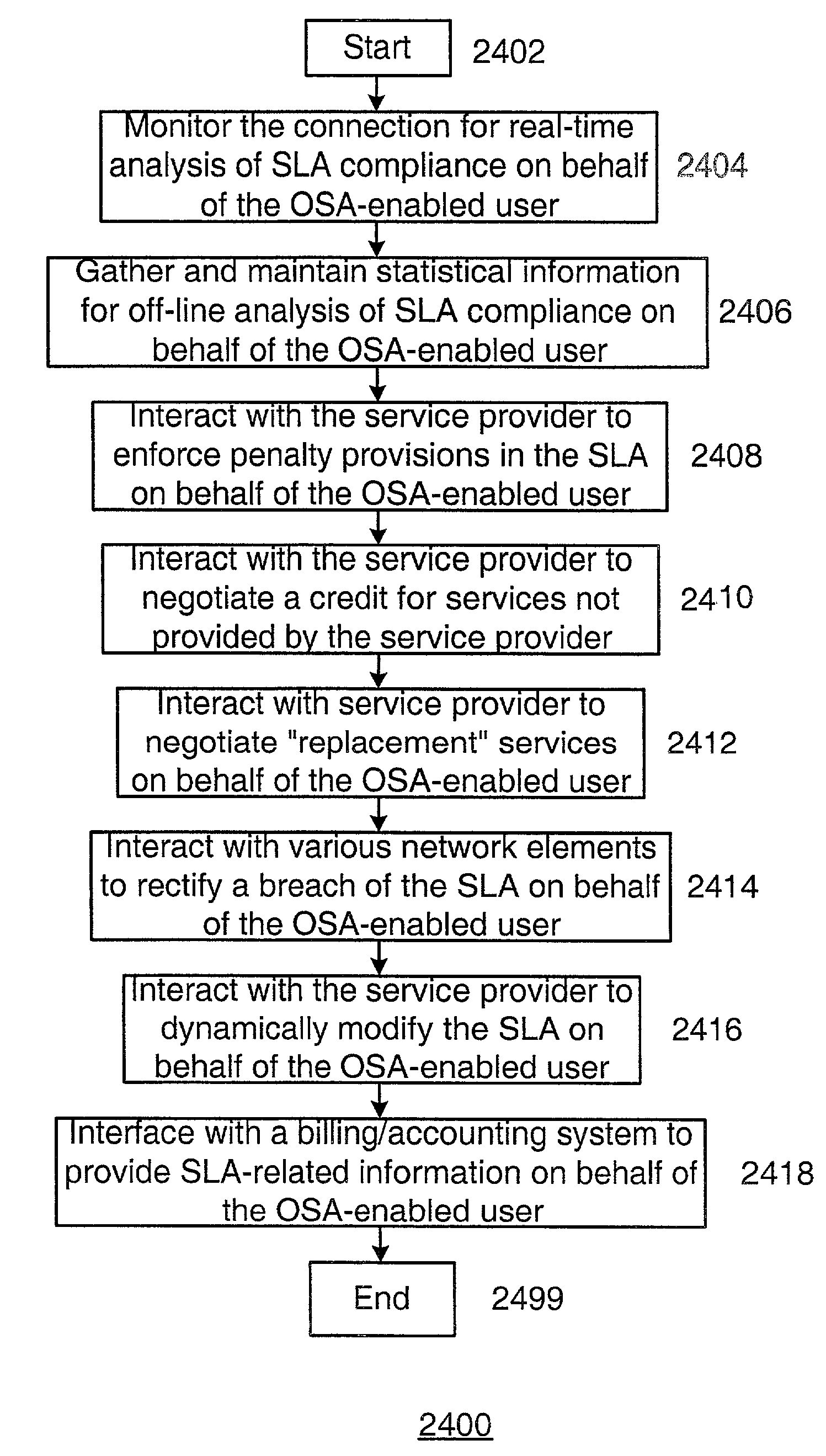
"The present invention is about an optical service agent that manages service level agreements for users. The agent can analyze connections in real-time and off-line to determine if the user is complying with the agreement. It can also negotiate with service providers to enforce penalties, negotiate credit for services not provided, and modify the agreement based on changing user requirements. The agent can also interface with billing / accounting systems to provide SLA-related information. Overall, the invention provides a more efficient and effective way to manage service level agreements for optical communication networks."

Problems solved by technology

Such optical communication networks provide vast amounts of bandwidth over short and long distances.
Traditionally, such communication services have been very expensive, and need to be planned and scheduled well in advance.
This is due in part because changes to the optical communication network, such as provisioning and switching optical communication paths, required substantial human intervention.

Method used


Image

  • System, device, and method for managing service level agreements in an optical communication system
  • System, device, and method for managing service level agreements in an optical communication system
  • System, device, and method for managing service level agreements in an optical communication system

Examples


Embodiment Construction

[0040]A SLA is essentially an agreement by a service provider to provide a specific level of service to the network user. The SLA is typically negotiated between the network user and the service provider prior to, or at the time of, establishing a connection. The SLA may provide for such things as connection bandwidth, connection quality (e.g., error rate, dropped packet rate, latency), connection duration, protection class, and protection / failover time, to name but a few. The SLA typically provides for various penalties in case the service provider is unable to provide the level of service agreed to in the SLA.

[0041]In typical “buyer beware” fashion, the network user is generally responsible for identifying any breaches of the SLA and invoking the penalty provisions of the SLA. Some breaches of the SLA are obvious, such as a complete failure of a connection. However, other breaches of the SLA are less obvious. Thus, the network user must typically police the SLA in order to identif...


PUM


Abstract

A system, device, and method for managing service level agreements in an optical communication system uses an optical service agent to manage a service level agreement (SLA) for a user. The optical service agent can perform both real-time and off-line analysis for the user, and can interact with various network elements (including the core optical communication network) to handle billing, penalty, and other issues associated with a SLA breach. Among other things, the optical service agent may monitor and analyze a connection in real-time for determining SLA compliance, gather and maintain statistical information relating to a connection, analyze the statistical information off-line for determining SLA compliance, patterns, and trends, interact with a service provider to enforce penalty provisions in the SLA, interact with a service provider to negotiate a credit for services not provided by the service provider in accordance with the SLA, interact with a service provider to negotiate “replacement” services for a breach of the SLA, interact with various network elements to rectify a breach of the SLA, interact with the service provider to dynamically modify the SLA based upon changing user requirements, and interface with a billing / accounting system to provide SLA-related information.

Description

PRIORITY[0001]The present application claims priority from the following commonly-owned United States patent application, which is hereby incorporated herein to by reference in its entirety:[0002]U.S. Provisional Patent Application No. 60 / 225,335 entitled OPTICAL SERVICE AGENT, which was filed on Aug. 15, 2000 in the names of Bruce A. Schofield, William R. Hawe, Paul D. Callahan, Indermohan Monga, Stephen Suryaputra, and Andre N. Fredette.CROSS-REFERENCE TO RELATED APPLICATION(S)[0003]The present application may be related to the following commonly-owned United States patent applications, which are hereby incorporated herein by reference in their entireties:[0004]U.S. patent application Ser. No. 09 / 931,643, now U.S. Pat. No. 7,283,747, entitled OPTICAL SWITCH ROUTER, which was filed on even date herewith in the names of Bruce A. Schofield, James V. Luciani, and Michael J. Craren;[0005]U.S. patent application Ser. No. 09 / 930,126, now abandoned, entitled SYSTEM AND DEVICE FOR PROVIDIN...

Claims


Application Information

Patent Timeline
Patent Type & Authority Patents(United States)
IPC IPC(8): G06F15/173G06F11/00H04J14/02H04L45/02H04Q11/00
CPCH04L12/24H04L41/00H04L41/046H04L41/32H04L41/5058H04Q11/0062H04J14/0238H04J14/0241H04B10/038H04J14/0227H04Q2011/0081H04L41/0893H04L41/5077H04Q11/0071H04Q2011/0079H04Q2011/0088H04J14/0284H04L41/34H04L41/0894H04L45/48
Inventor MONGA, INDERMOHAN S.SCHOFIELD, BRUCE A.TYAGI, RAJESH
Owner RPX CLEARINGHOUSE
Learn More