
Ventilatory assistance using an external effort sensor

a technology of effort sensor and ventilator, which is applied in the direction of valves, respirators, mechanical devices, etc., can solve problems such as unreliability of measures, and achieve the effects of improving patient-machine synchronization, robustness and ease of use, and improving patient-machine synchronization

Inactive Publication Date: 2006-09-05
RESMED LTD
View PDF37 Cites 111 Cited by
  • Summary
  • Abstract
  • Description
  • Claims
  • Application Information

AI Technical Summary

Benefits of technology

This patent describes various advantages of different methods for measuring breathing efforts during mechanical ventilation. The technical effect of this innovation is improved patient-device synchronization by eliminating leaks and providing more accurate signals quickly after initiating muscle activity. Non-invasive techniques like monitoring nasal pressures are easier than traditional methods and can provide reliable data. Chest movements have multiple degrees of freedom which make them less useful for measurement.

Problems solved by technology

The technical problem addressed in this patent text relates to finding better ways to assess the amount of physical effort required for breathing in individuals who suffer from diseases affecting the lungs or chest walls. Existing methods rely on indirect measurements like nasal pressure or pulmonary function, leading to errors caused by variations in those quantities. Additionally, there are issues with measuring patient effort while they are relaxed or falling asleep. This makes it challenging to accurately adjust the levels of support provided through ventilators without compromising effectiveness or safety.

Method used


Image

  • Ventilatory assistance using an external effort sensor
  • Ventilatory assistance using an external effort sensor
  • Ventilatory assistance using an external effort sensor

Examples


Embodiment Construction

[0026]1. Suprasternal Notch Optical Effort Sensor

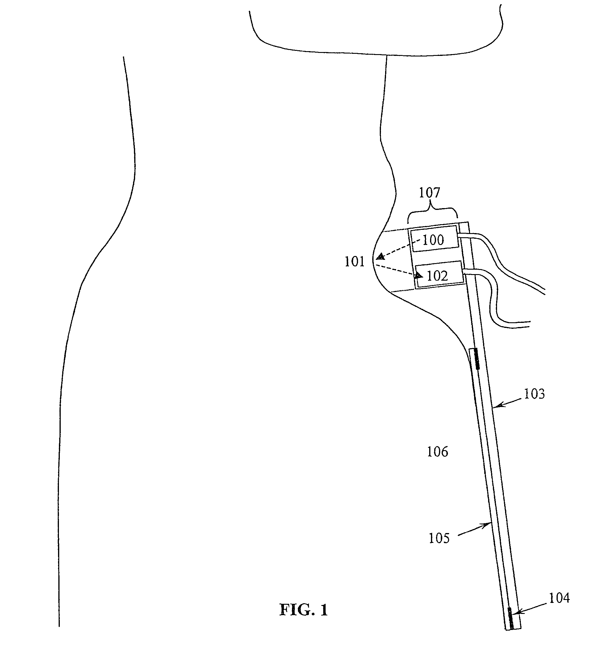
[0027]The preferred embodiment of the present invention uses an optical sensor, such as an infrared proximity sensor, to measure the depth of the suprasternal notch, as shown in FIG. 1. A light source 100 shines light on the skin of the suprasternal notch 101, and the reflected light is received by photocell 102. (The term “photocell” is used to refer to any device whose output is light sensitive, e.g., a photodiode, phototransistor, etc.) The combined sensor assembly 107 may be mounted on any surface which is relatively immobile with respect to the skin of the suprasternal notch, such as the sternum 106. A suitable method for attachment is to mount the sensor 107 on cantilever 103, which is then glued to the sternum using double-sided adhesive tape 104.

[0028]Preferably, the double-sided adhesive tape is not glued directly to the skin, but is glued to a layer of soft, spongy, low irritant, low allergenic self-adhesive material 105. A ...


PUM


Abstract

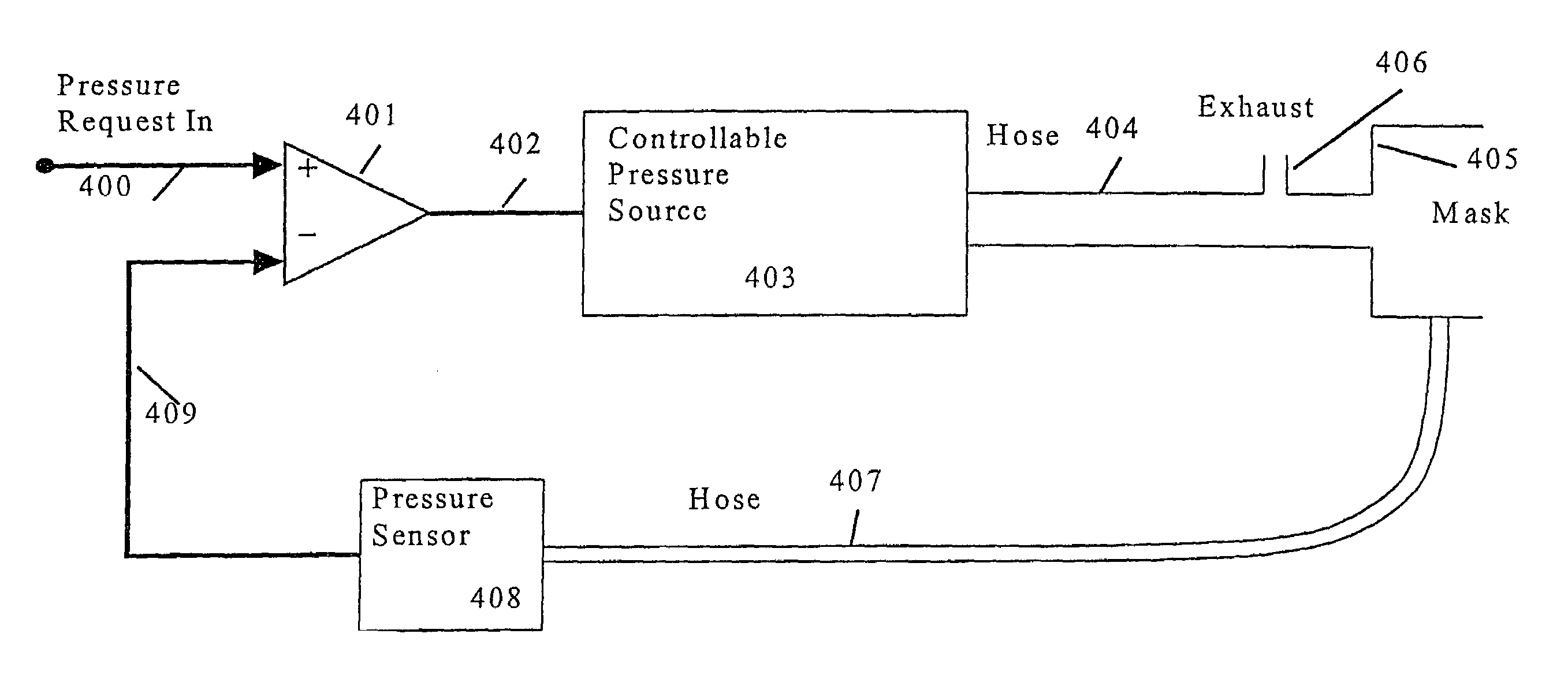
The ventilator of the invention uses a respiratory effort sensor that does not rely on respiratory airflow or pressure for synchronization, such as a device that measures movement of the suprasternal notch in response to respiratory efforts. This makes the ventilator relatively immune to leaks. Furthermore, the mask pressure may be modulated so as to servo-control the respiratory effort signal to be zero. Because effort is servo-controlled to be near zero, it is not necessary for the effort signal to be either linear or calibrated, but merely monotonic on effort. Similarly, it is possible to achieve near 100% assistance without having to know or estimate the resistance and compliance of the patient's respiratory system, as in those systems that provide proportional assist ventilation.

Description


Claims


Application Information

Patent Timeline
Owner RESMED LTD
Learn More