Downhole ball dropping apparatus

a technology of ball dropping apparatus and downhole, which is applied in the direction of fluid removal, sealing/packing, borehole/well accessories, etc., can solve the problems of high pressure spikes, ball may not release, and premature release of ball

Inactive Publication Date: 2006-09-05
BAKER HUGHES INC
View PDF19 Cites 31 Cited by
  • Summary
  • Abstract
  • Description
  • Claims
  • Application Information

AI Technical Summary

Benefits of technology

[0004]A ball release mechanism is mounted near the intended seat. The ball or balls are kept out of the circulating stream. High circulation rates followed by curtailment of circulation places an outlet port in po...

Problems solved by technology

Several problems can occur with this design.
The ball may not release because the carrier gets clogged with debris from the mud.
The carrier can become worn resulting in premature release of the ball.
It can sl...

Method used


Image

  • Downhole ball dropping apparatus
  • Downhole ball dropping apparatus

Examples


Embodiment Construction

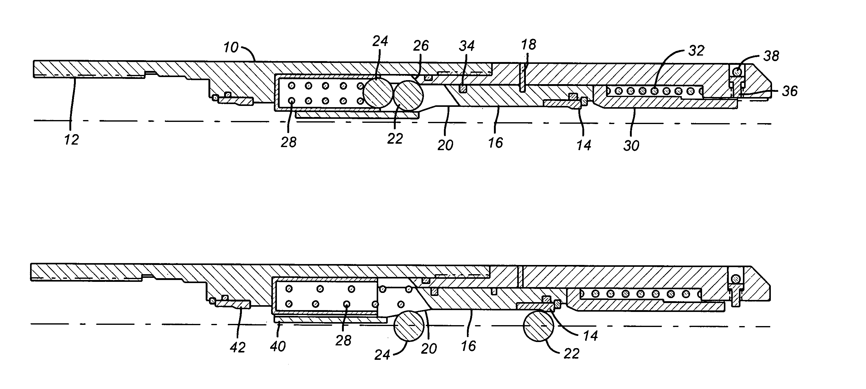
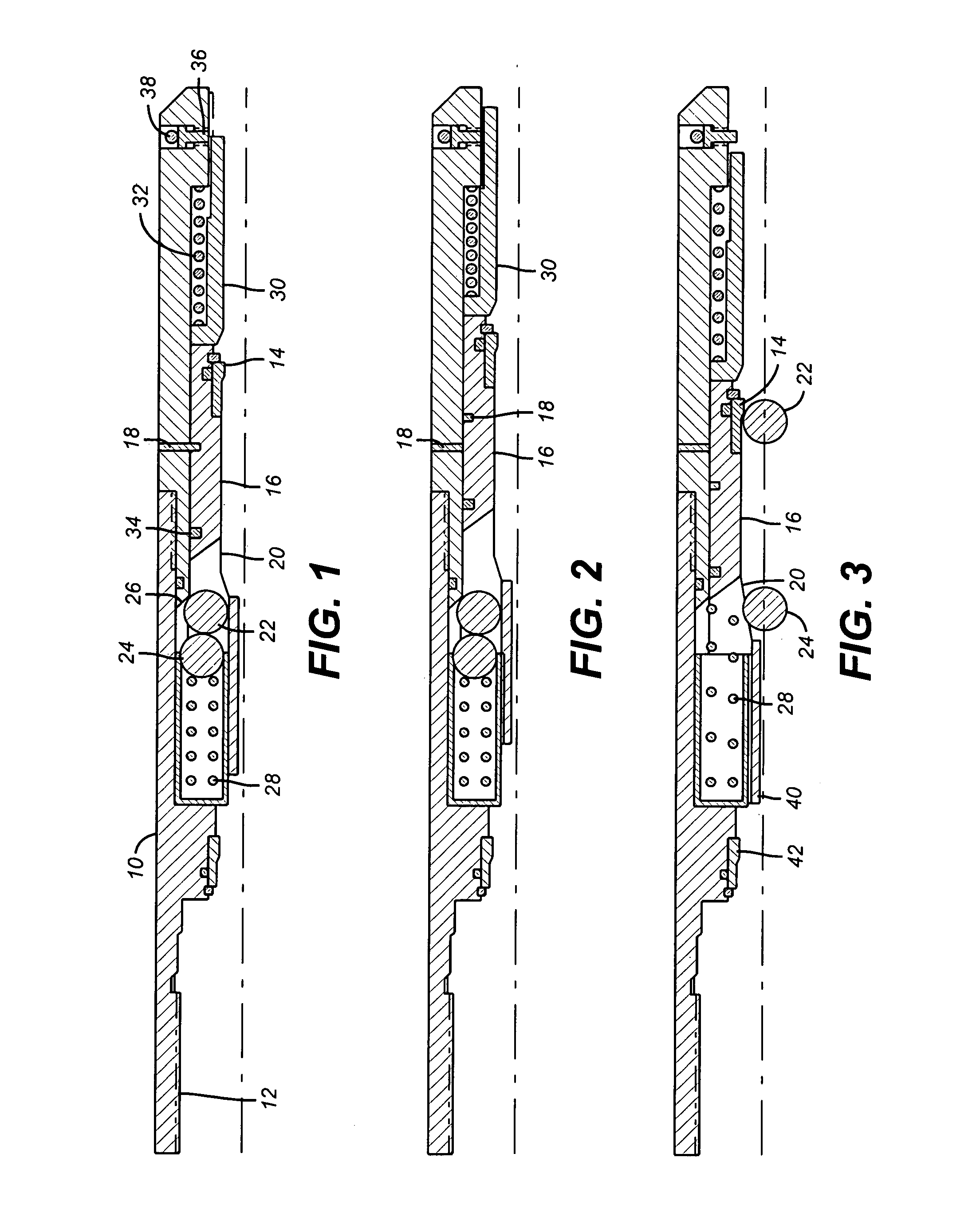
[0008]Referring to FIG. 1, a housing 10 is connected at thread 12 to a string and downhole equipment (not shown). Housing 10 comprises a primary ball seat 14 preferably mounted on ball carrier 16 or in another housing in fluid communication with housing 10. As illustrated, ball seat 14 provides resistance to circulation to move the ball carrier 16. However, that resistance can be from another constriction on ball carrier 16 with the ball seat in another housing in fluid communication with housing 10. In the preferred embodiment, the balls 22 and 24 drop less than a meter to get to ball seat 14. A shear pin 18 initially holds the ball carrier 16 to the housing 10. In the run in position, an outlet port 20 is so positioned that balls 22 and 24 cannot escape. Balls 22 and 24 are biased toward tapered surface 26 on ball carrier 16 by spring 28. Housing 10 further comprises a sleeve 30 biased by spring 32 toward ball carrier 16. A seal 34 seals between ball carrier 16 and housing 10. For...


PUM


Abstract

A ball release mechanism is mounted near the intended seat. The ball or balls are kept out of the circulating stream. High circulation rates followed by curtailment of circulation places an outlet port in position to allow the ball or balls to be pushed out by a spring. The spring or one of the balls prevents the return of an ejected ball back into the protected pocket. The ball is delivered to the seat without circulation.

Description

FIELD OF THE INVENTION[0001]The field of the invention is a ball release device and more particularly a device that is mounted near the hole bottom with the stored ball or balls protected until release after circulation.BACKGROUND OF THE INVENTION[0002]Most prior ball release devices store the ball in the fluid stream and use circulation to transport it to the seat. Several problems can occur with this design. The ball may not release because the carrier gets clogged with debris from the mud. The carrier can become worn resulting in premature release of the ball. The ball is released during high circulation. It can slam against a seat and create high pressure spikes that can damage other equipment. The high circulation rates around the ball can erode parts of it causing it to not hold pressure even if it lands on the ball seat. Some examples of prior designs that have the ball in the circulating path are U.S. Pat. Nos. 6,390,200; 6,220,360; and 5,960,881. U.S. Pat. No. 4,171,019 sho...

Claims


Application Information

Patent Timeline
IPC IPC(8): E21B33/12E21B21/10E21B23/04E21B34/08E21B34/14
CPCE21B21/10E21B34/14E21B34/08E21B23/04E21B34/142
Inventor DAVIS, JOHN P.LYNDE, GERALD D.
Owner BAKER HUGHES INC
Why Eureka
Try Eureka