Combustor liner with inverted turbulators

a combustor and inverter technology, applied in the field of turbine components, can solve the problems of large nox emissions, premature film cooling of the combustor liner and transition piece, and the flame temperature is still too hot for prior conventional combustor components to withstand, so as to reduce the pressure loss

Inactive Publication Date: 2006-09-12
GENERAL ELECTRIC CO
View PDF72 Cites 68 Cited by
  • Summary
  • Abstract
  • Description
  • Claims
  • Application Information

AI Technical Summary

Benefits of technology

The invention describes how this new type of engine part helps reduce friction by designing its outer surface to have less resistance for air flow. This results in better performance and efficiency for the engine.

Problems solved by technology

The technical problem addressed in this patent is how to effectively cool down the combustor liner and transition piece in gas turbines without causing excessive pressure drop and damage to the materials. Traditionally, these parts were cooled using film-cooling technology, but new methods are needed due to advances in engine design that reduce the availability of cooling air.

Method used


Image

  • Combustor liner with inverted turbulators
  • Combustor liner with inverted turbulators
  • Combustor liner with inverted turbulators

Examples


Embodiment Construction

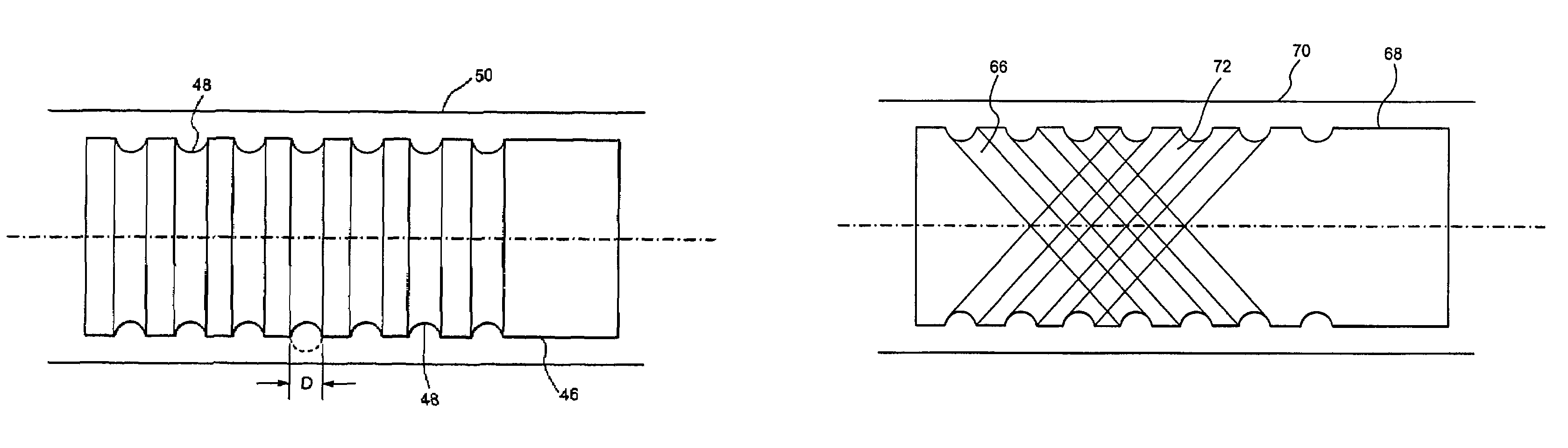
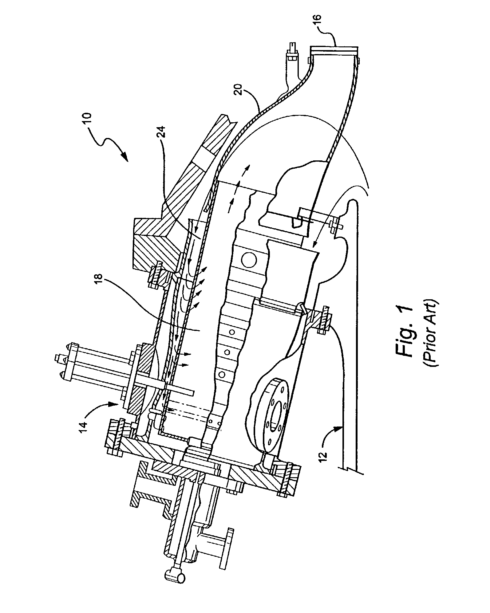
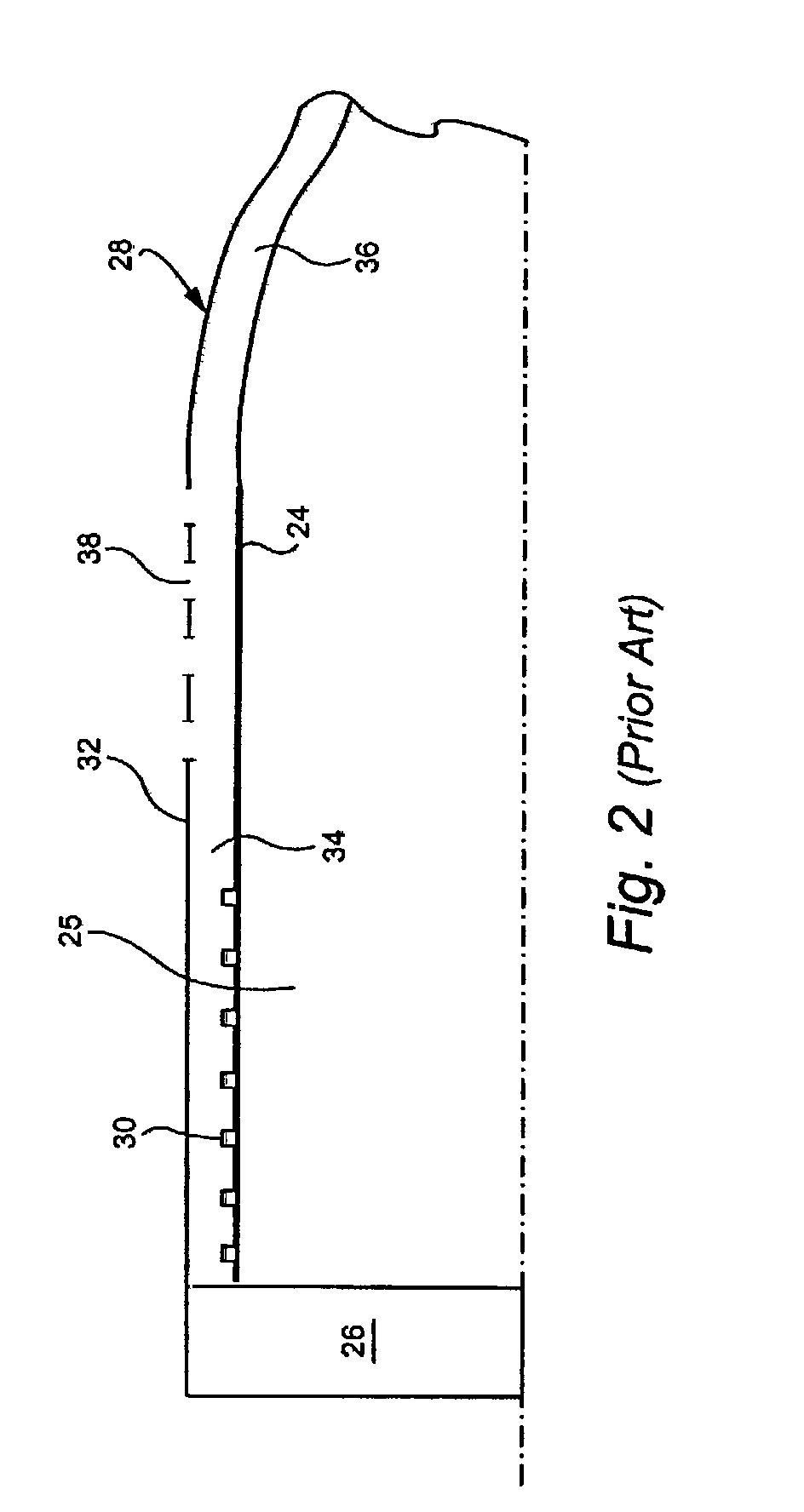
[0021]FIG. 1 schematically illustrates a typical can annular reverse-flow combustor 10 driven by the combustion gases from a fuel where a flowing medium with a high energy content, i.e., the combustion gases, produces a rotary motion as a result of being deflected by rings of blading mounted on a rotor. In operation, discharge air from the compressor 12 (compressed to a pressure on the order of about 250–400lb / in2) reverses direction as it passes over the outside of the combustors (one shown at 14) and again as it enters the combustor en route to the turbine (first stage indicated at 16). Compressed air and fuel are burned in the combustion chamber 18, producing gases with a temperature of about 1500° C. or about 2730° F. These combustion gases flow at a high velocity into turbine section 16 via transition piece 20. The transition piece connects to the combustor liner 24 at 22, but in some applications, a discrete connector segment may be located between the transition piece 20 and ...


PUM


Abstract

A combustor liner for a gas turbine, the combustor liner having a substantially cylindrical shape; and a plurality of axially spaced circumferential grooves formed in an outside surface of the combustor liner.

Description


Claims


Application Information

Patent Timeline
Owner GENERAL ELECTRIC CO
Why Eureka
Try Eureka