Method and a coupler for joining two steel pipes

a technology of two steel pipes and couplers, applied in the direction of hose connection, cable termination, manufacturing tools, etc., can solve the problem of over-stressing of the join

Inactive Publication Date: 2006-09-19
ARANT AS TRUSTEE MR GENE W +1
View PDF44 Cites 83 Cited by
  • Summary
  • Abstract
  • Description
  • Claims
  • Application Information

AI Technical Summary

Benefits of technology

[0011]Applicant also provides a method of flaring thermoplastic pipe sections such that the flared end sections of such pipe may be used with Ap...

Problems solved by technology

This manner of joining together steel pipe often results in the weakest point in the pipeline res...

Method used


Image

  • Method and a coupler for joining two steel pipes
  • Method and a coupler for joining two steel pipes
  • Method and a coupler for joining two steel pipes

Examples


Embodiment Construction

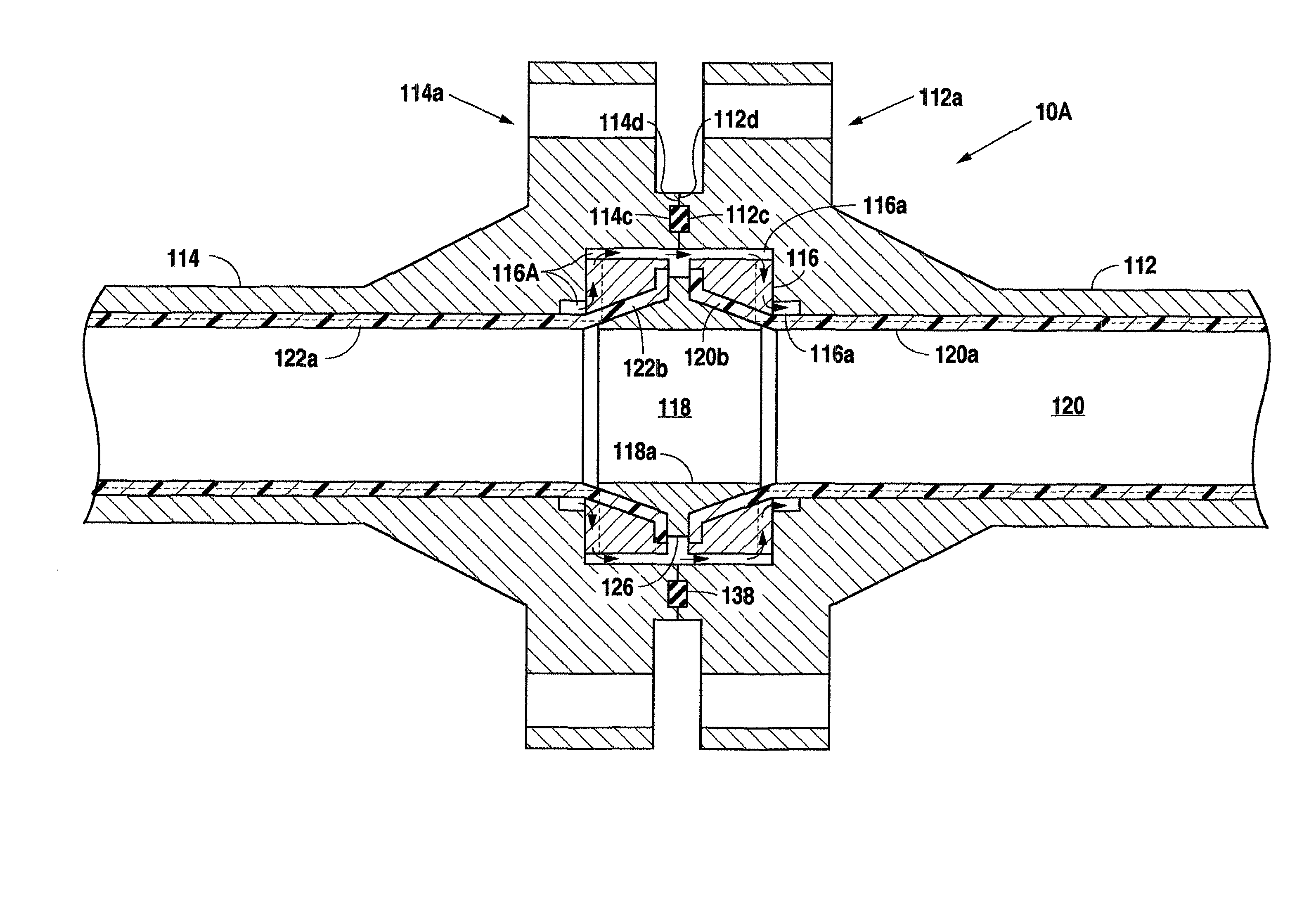
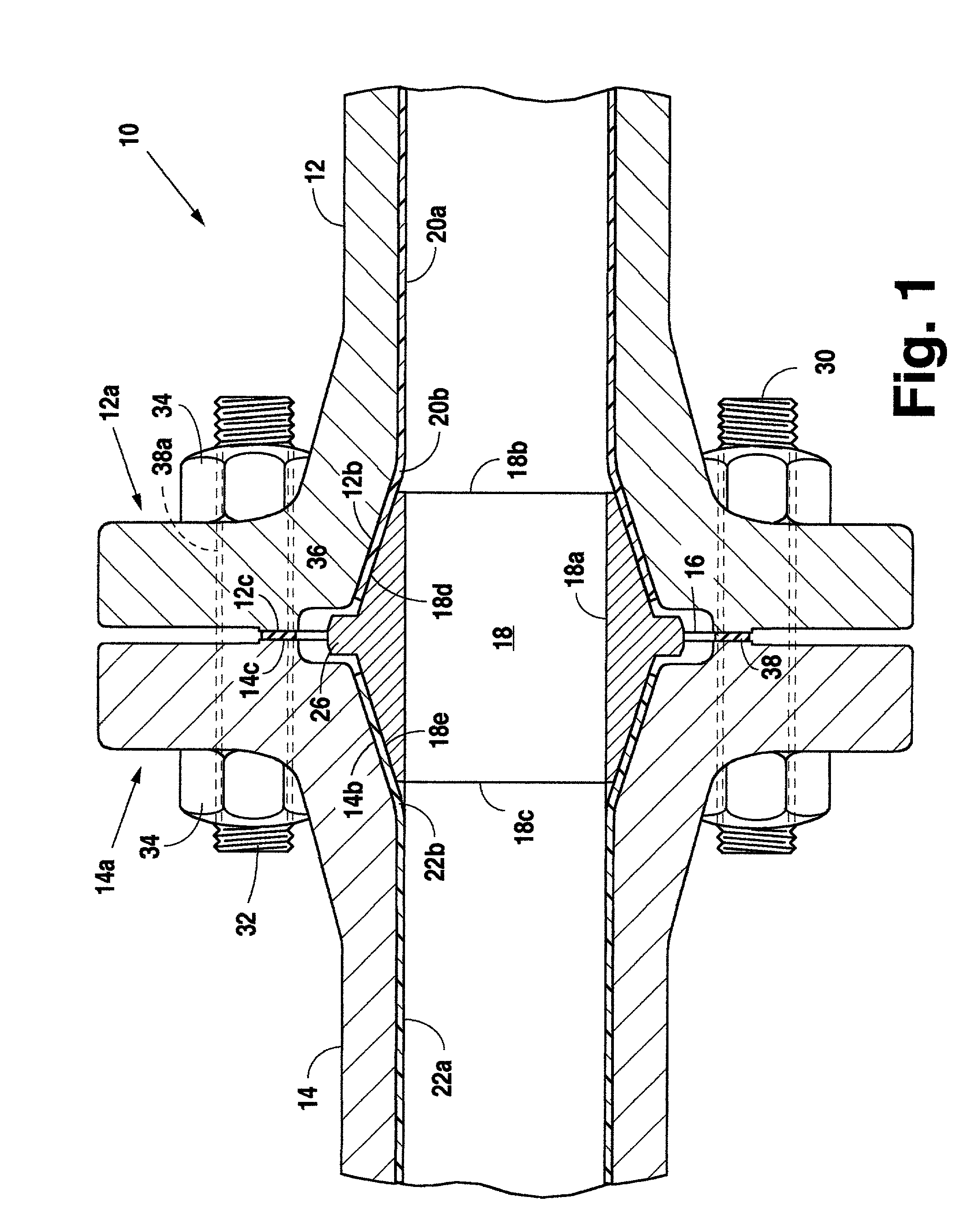
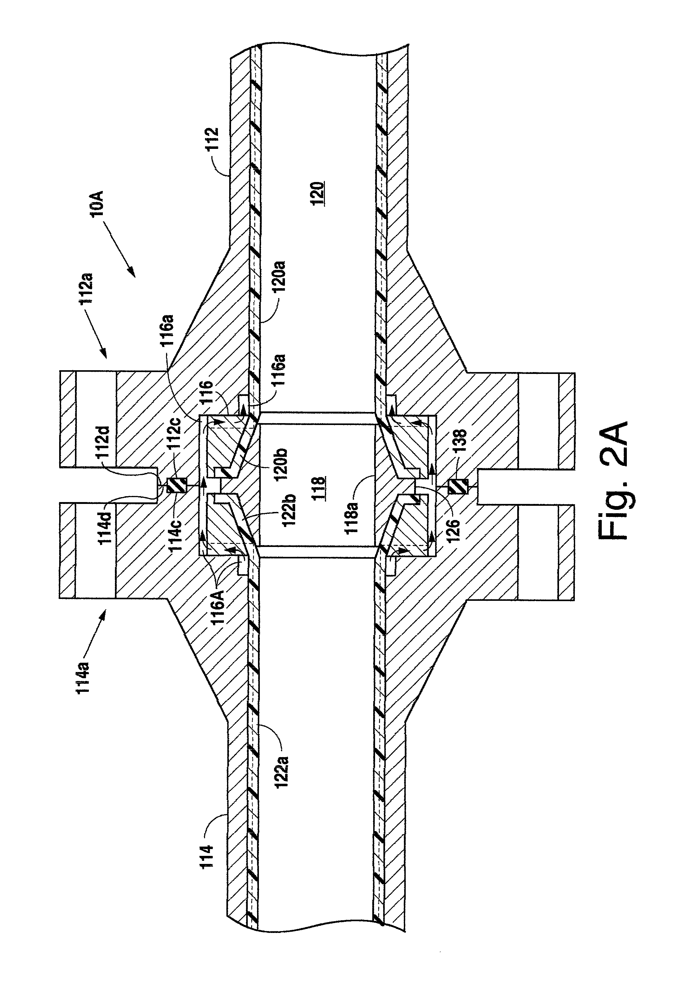
[0025]The sealing system of the present invention is designed to maintain a fluid tight seal once in place. With reference to FIG. 1, a sealed joint (10) is illustrated wherein a first pipe (12) having a first flanged end (12a) is joined together with a second pipe (14) having a first flanged end (14a). The first flanged end (12a) of the first pipe (12) has a milled internal surface (12b) sufficiently milled to accept the coupler (18) to be inserted into the joint (10). The first flanged end (14a) of the second pipe (14) also has a milled internal surface (14b) sufficiently milled to accept the coupler (18) to be inserted into the joint (10). The surfaces are typically milled to angles of between 5° and 45° as measured from the horizontal as viewed in FIG. 1. Coupler (18) matches the milling angle as set forth in more detail below and as is evident when viewing FIG. 1. The first flanged end (12a) of the first pipe (12) typically abuts the first flanged end (14a) of the second pipe (...


PUM

PropertyMeasurementUnit
Flow rateaaaaaaaaaa
Diameteraaaaaaaaaa
Permeabilityaaaaaaaaaa

Abstract

A method and apparatus for coupling together the ends of two steel pipe sections, each of which contains a permeable inner liner, in which not only are the pipe ends held in abutting engagement, but gas contained within the liner of one pipe section is effectively channeled into the liner of the other pipe section.

Description

[0001]This application is based on and claims priority from provisional patent application Ser. No. 60 / 257,415, filed Dec. 21, 2000.FIELD OF THE INVENTION[0002]A method for joining two steel pipes and a coupler for affecting the same, more specifically a method for joining two steel pipes using a coupler with a milled, tapered inner surface.BACKGROUND[0003]The present invention is herein described as an apparatus and method used to join pipe, including steel pipe, together which utilizes the structural strength of the adjoining pipes and enables the junction of two steel pipes to be operated safely under high pressure. The effective operation and safety of pipelines is required in the industry. For example, pipelines utilized the world over convey oil, water and gas from source to distributors to consumers. The integrity of these pipelines is of paramount importance to our economy and safety.[0004]This invention relates to the pipeline industry where steel pipe is commonly used. Ste...

Claims


Application Information

Patent Timeline
IPC IPC(8): B23P11/00F16L55/00
CPCF16L23/125F16L23/167Y10T29/4987Y10T29/49908Y10T29/49872
Inventor LEVARIO, ALFREDO
Owner ARANT AS TRUSTEE MR GENE W
Why Eureka
Try Eureka